
Car Anti-Theft System
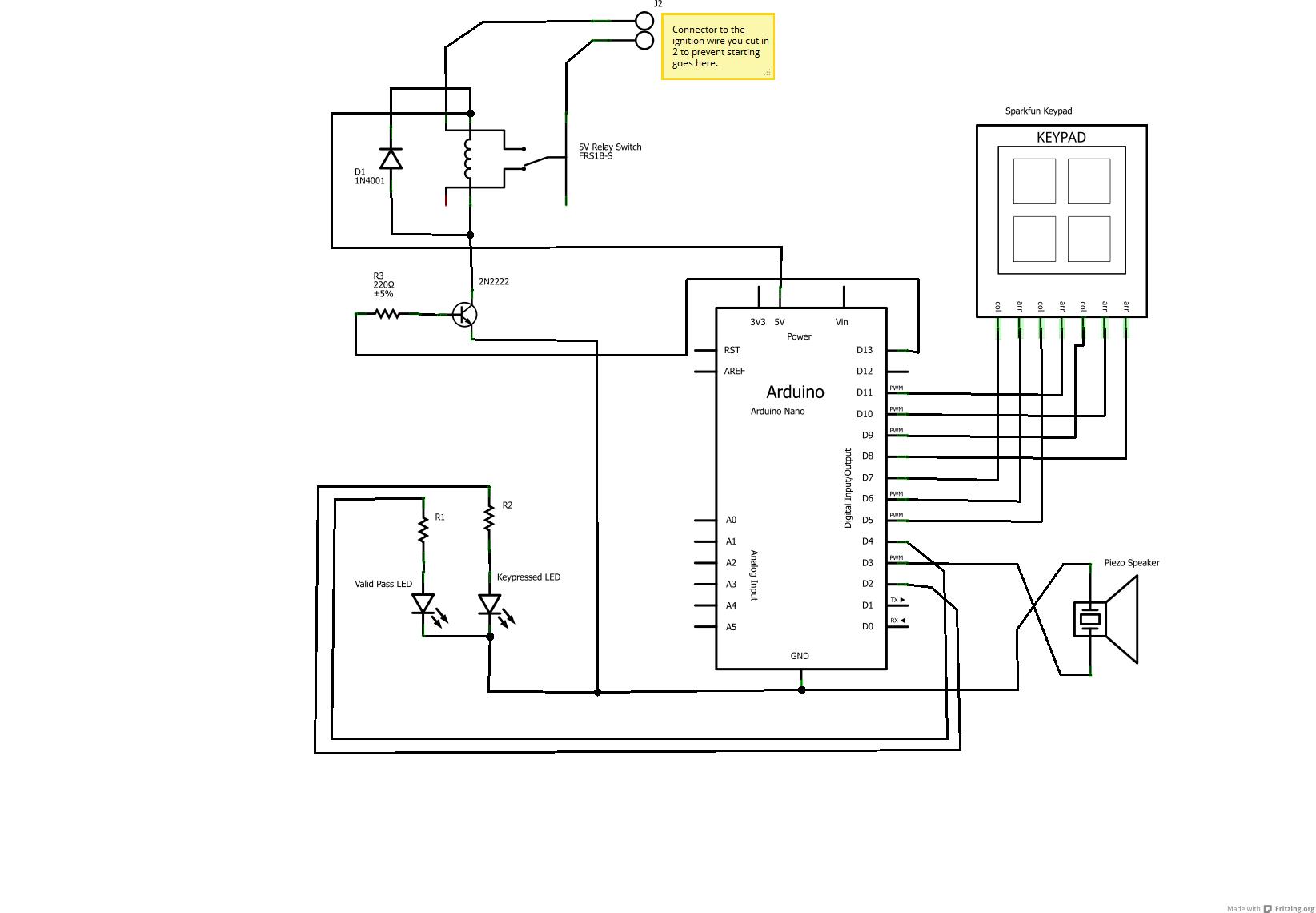
The described electronic schematic involves several components and connections that facilitate a secure ignition system for a vehicle. The Arduino microcontroller serves as the central processing unit, interfacing with a keypad for user input and a piezo speaker for audio feedback. The two LEDs provide visual cues indicating the success or failure of the entered keycode. The relay controlled by the 2N2222 transistor operates as a switch, reconnecting the Ignition Signal Line to the vehicle’s computer when the correct keycode is entered.
The power supply to the Arduino is managed through an LM7805 voltage regulator, which steps down the vehicle's accessory voltage to a stable 5V. This regulator is crucial for ensuring that the Arduino operates reliably without depleting the car's battery when the ignition is off. The USB hub located under the dashboard allows for the integration of additional peripherals, enhancing the system's functionality for future upgrades.
The installation process involves identifying and cutting the ISL, which is critical for the operation of the anti-start feature. The relay's role is to restore the ISL connection when the correct keycode is input, allowing the vehicle to start. The accessory wire must be carefully located to ensure that the Arduino powers on only when the ignition is in the ACC position, preventing unnecessary power drain.
Overall, this schematic represents a compact and efficient solution for vehicle security, combining user-friendly interfaces with robust electronic components to create a reliable ignition control system.Audible signals will alert you if password/keycode entered is Accepted or not ( in this case, some random for wrong and Super Mario Song for success) via a standard piezo speaker. 2-The under-dashboard USB hub is perfect for future dev or embeded device like GPS or Bluetooth headset as this one has 7 ports on which power and data can be streamed.
( A usb plug next to the OBDII, sweet) As you can see, it`s pretty straight forward, Arduino reads the keypad, every press trigger some sound via piezo, 2LEDs for feedback and a relay driven with a 2N2222 transistor and protected by a diode (THIS IS IMPORTANT, see why here ) So Arduino is plugged in via USB cable and get nice 5V juice out of it. Also, it enable the software update by plugging the HUB to any laptop and the addition of 6 other USB powered devices.
The solution was to cut the wall-wart and replace it with a LM7805 on perfboard which is itself plugged into the accessory line o the car, this way the arduino is up after you turn the key on, thus less battery usage. As explained above, all what is needed to prevent the car from starting up is to cut the Ignition Signal Line ISL from the Car Key Connector.
When this cable is not connected and you turn the key to start, the signal won`t reach the computer so no vroom. This is where a relay comes in handy as it will reconnect this wire and thus provide ignition. 3-Locate the Accessory wire (on the pic it`s the big beefey orange one) by probing on ground and on all the other wires and by turning the key to ACC.
to have power only when it`s on this position and connect LM7805 V+ here 4-Locate the ISL again by grounding one lead of your Multi and by probing each wire then turning the key to start your car. When you find the correct wire, cut it and try to start, if it fails, you succeed. 6-Plugin, make it look shiny and punch in a keycode, if the relay tick, you got that time to start your car.
Don`t worry about the current as it`s a Signal line (well, it is on a Yaris) and some low voltage goes through). 🔗 External reference
Related Circuits
A newer version of this circuit board is available. Rev 4 includes a faster CPU, more memory, more I/O, and an optional LCD. It is recommended to use Rev 4 for new projects. Although the older board is no...
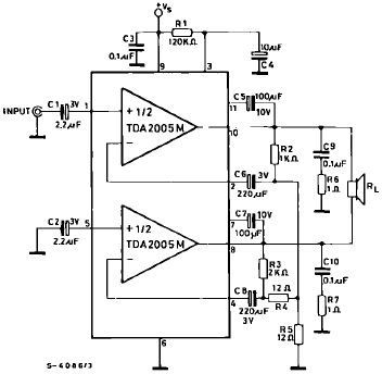
The TDA2005 is a Class B dual audio power amplifier package specifically designed for car radio applications. It facilitates the easy design of car radio power boosters. The TDA2005 power amplifier is engineered to deliver high-quality audio output in automotive...
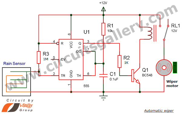
Have you seen Audi, Lexus, or Ford rain-sensing wipers and wondered how they operate in these vehicles? They are controlled by sensors located at the center of the windscreen, which detect raindrops and activate the wiper motor. The functioning...
This is a diagram of a car audio active loudspeaker utilizing the LF353 operational amplifier from National Semiconductor. For optimal performance, the NE5532 is recommended to split the audio signal into three frequency bands using an active filter. The...
An article discusses a do-it-yourself radar system constructed using the PIC18F452 microcontroller. This project is suitable for hobbyists, although the schematic details are not provided. The do-it-yourself radar system utilizing the PIC18F452 microcontroller presents an engaging project for electronics enthusiasts....
The TL494 controls a car's audio inverter power supply, which is a high-fidelity audio power supply designed for custom vehicles. It operates reliably without the need for adjustments according to the provided circuit diagram. The TL494 is a versatile integrated...