
Car Interior Lights Delay

The circuit design utilizes a combination of transistors, resistors, a capacitor, and a diode to create a delayed lighting effect for the interior of a vehicle. The core components include:
1. **Transistor T1**: This transistor acts as a switch that controls the operation of T2 based on the door switch's state. When the door is closed, T1 is activated, preventing current from flowing to T2 and keeping the interior lights off.
2. **Transistor T2**: This is the main driver for the interior lights. When T1 is off (door open), T2 is activated, allowing current to flow to the lights.
3. **Capacitor C1**: This component is crucial for the delay effect. It charges quickly when the door is opened, enabling T2 to turn on the lights. The slow discharge through R5 creates the gradual dimming effect once the door is closed.
4. **Resistors R3 and R5**: R3 controls the charging rate of C1, while R5 governs the discharge rate. Adjusting these resistors changes the timing of the light delay.
5. **Diode D1**: This diode allows current to flow in one direction, ensuring that C1 charges properly without discharging back through the circuit.
6. **IC2 (MOSFET)**: The selected MOSFET must handle high voltages to ensure reliability. The BUZ74 is a suitable choice due to its high voltage rating, making it capable of managing the power requirements of the interior lighting system.
The circuit's operation can be summarized as follows: when the door opens, T1 turns off, allowing C1 to charge through R3 and D1, which activates T2 and turns on the interior lights. Once the door closes, T1 turns on, stopping the charging of C1. The slow discharge through R5 keeps T2 active momentarily, allowing the lights to stay on before gradually dimming. This design enhances user convenience, particularly in low-light situations, by providing a more user-friendly experience when entering or exiting the vehicle.Most cars do not have delayed interior lights. The circuit presented can put this right. It switches the interior lights of a car on and off gradually. This makes it a lot easier, for instance, to find the ignition keyhole when the lights have gone off after the car door has been closed. Since the circuit must be operated by the door switch, a sli ght intervention in the wiring of this switch is unavoidable. When the car door is opened, the door switch closes the lights circuit to earth. When the door is closed (and the switch is open), transistor T1, whose base is linked to the switch, cuts off T2, so that the interior light remains off. When the switch closes (when the door is opened), the base of T1 is at earth level and the transistor is off.
Capacitor C1 is charged fairly rapidly via R3 and D1, whereupon T2 comes on so that the interior light is switched on. When the door is closed again, T1 conducts and stops the charging of C1. However, the capacitor is discharged fairly slowly via R5, so that T2 is not turned off immediately. This ensures that the interior light remains on for a little while and then goes out slowly. The time delays may be varied quite substantially by altering the values of R3, R5, and C1. Circuit IC2 may be one of many types of n-channel power MOSFET, but it should be able to handle drain-source voltages greater than 50 V.
In the proto-type, a BUZ74 is used which can handle D-S voltages of up to 500 V. 🔗 External reference
Related Circuits
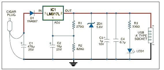
This USB car charger adapter project functions as a DC-DC power converter that effectively converts the 12V car battery voltage into a stable 5V output. It is designed to supply power from a car's cigar lighter socket to any...
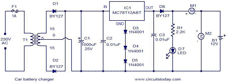
Below is a simple circuit designed for charging car batteries. This circuit includes the capability to monitor both the charging current and voltage. It utilizes the IC MC78T12ABT from Freescale, which is essentially a 7812 in a TO-3 package...
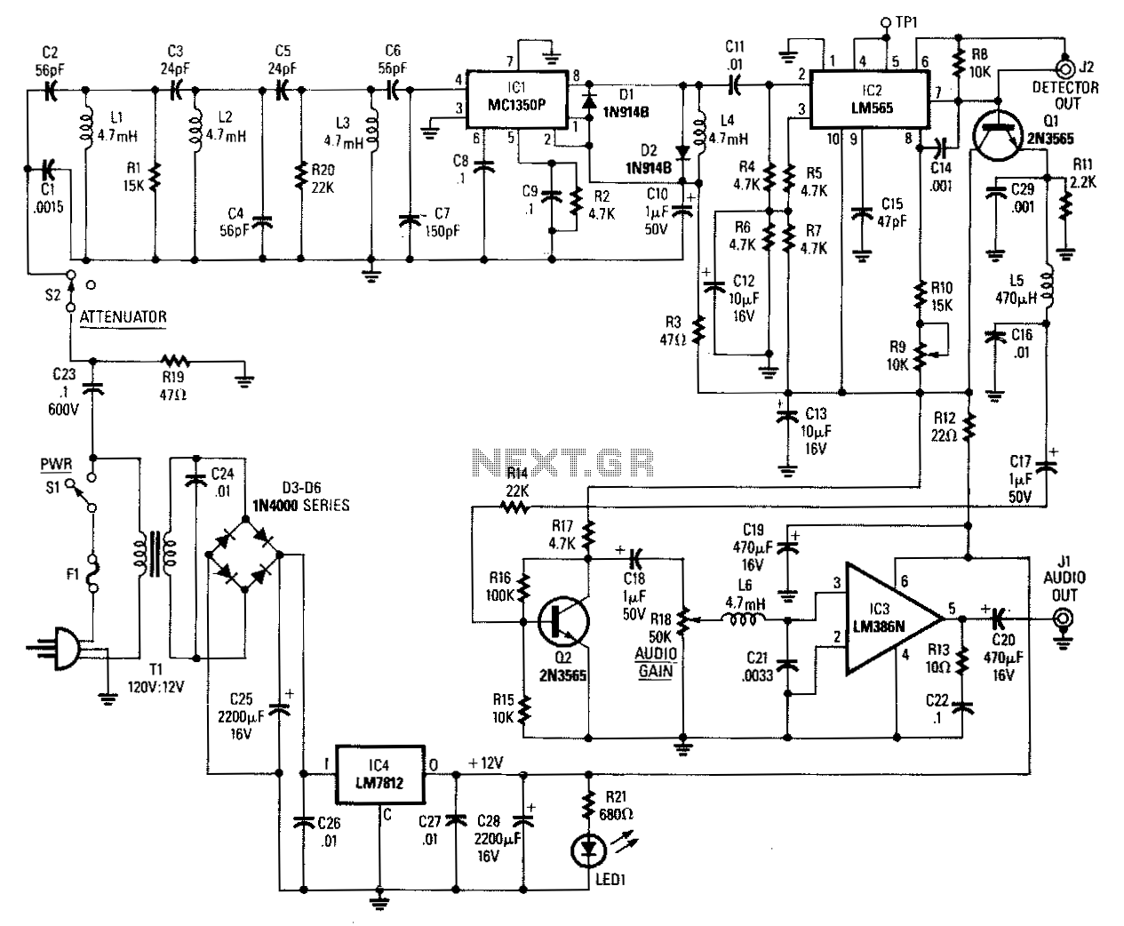
Input signals from the power line are coupled through C23 and R19 to the input filter network. C23 must be rated at 600 volts. Switch 52 is used as an attenuator. Components C2 through C7, L1 through L3, R1,...
There are at least three different versions of this circuit. The first DM-2 version utilized the MN3005 BBD and the MN3101 Clock Driver IC (PCB marking: ET5214-510). Later, the clock driver was changed to the MN3102, and the BBD...
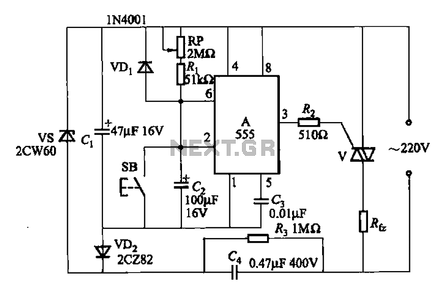
A 555 four-base integrated circuit delay circuit is designed to facilitate a transition from high to low output. When the button SB is pressed, the output is set to high, and after a specified delay, the output transitions to...
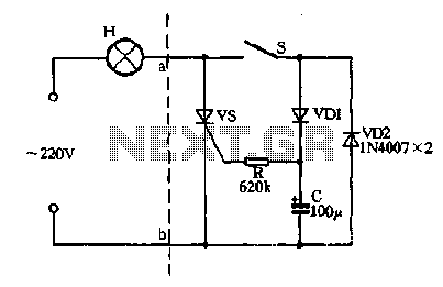
Closing the switch S allows the AC positive half-cycle to flow through diode VDI and resistor R, causing the SCR to open simultaneously at both ends of the capacitor C, which becomes fully charged. During this phase, the positive...
Warning: include(partials/cookie-banner.php): Failed to open stream: Permission denied in /var/www/html/nextgr/view-circuit.php on line 713
Warning: include(): Failed opening 'partials/cookie-banner.php' for inclusion (include_path='.:/usr/share/php') in /var/www/html/nextgr/view-circuit.php on line 713