
Car Lights Monitor
The automotive lighting monitoring circuit employs two Telefunken ICs, specifically designed to detect current flow through light bulbs, thereby indicating their operational status. The circuit's design utilizes a series resistor placed alongside the bulb to create a measurable voltage drop when the bulb is activated. This voltage drop is critical for the IC's functionality, as it allows the IC to compare the voltage against an internal reference, ensuring accurate detection of the bulb's status.
For practical implementation, the circuit requires careful selection of the series resistor's value based on the bulb's power rating and the vehicle's battery voltage. The calculations provided illustrate the relationship between the bulb's wattage, the supply voltage, and the required resistance to achieve the necessary voltage drop for each specific IC model. The use of resistance wire or standard circuit wire for the series resistor provides flexibility in sourcing materials, while also accommodating the potential for existing vehicle wiring to suffice as the series resistor.
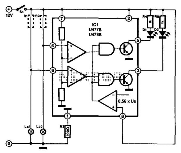
The output pins of the ICs allow for the integration of visual indicators, such as LEDs, which serve as alerts for bulb failures. This feature enhances the circuit's utility, providing immediate feedback to the vehicle operator regarding the status of critical lighting components. Overall, this circuit represents a robust solution for automotive lighting monitoring, leveraging precise measurements and effective signaling to ensure vehicle safety. This circuit is for the purpose of monitoring automotive lighting. Two special ICs are available from Telefunken that ar e designed to measure the current through a light bulb. In practice, detecting whether a current flows through a bulb or not is a most suitable way of determining whether the bulb still works. If a small resistance is connected in series with a bulb, a small voltage drop will develop across it when the bulb lights (R1 and R2 in the diagram).
Each IC can cope with only two bulbs, so three or four ICs are needed per car. The junction of the bulb and resistor is connected to one of the inputs (pin 4 or pin 6) of the IC. The potential across the resistor is compared in the IC with an internal reference voltage. Depending on which of the two ICs is used, the voltage drop must be about 16 mV (U477B) or 100 mV (U478B). This voltage drop is so small that it will not affect the brightness of the relevant bulb. The value of the series resistor is determined quite easily. If, for instance, it is in series with the brake light (normally 21 W), the current through the bulb, assuming that the vehicle has a 12-V battery, is 21-r 12 = 1.75 A.
The resistance must then be of 16^-1.75 = 9 mQ (U477B) or 100-r 1.75 = 57 mU (U478B). These resistors can be made from a length of resistance wire (available from most electrical retailers). Failing that, standard circuit wire of 0.7 mm diameter can be used. This has a specific resistance of about 100 mQ per meter. However, in most cars, the existing wiring will have sufficient resistance to serve as series resistor.
LEDs can be connected to the outputs of the IC (pins 3 and 5). These will only light if the relevant car light fails to work properly. 🔗 External reference
Related Circuits
This circuit utilizes the widely available and user-friendly LM3914 integrated circuit (IC). The LM3914 is straightforward to operate, does not require external voltage regulators due to its built-in voltage regulation, and can be powered by nearly any voltage source....
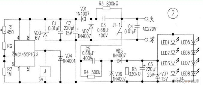
The circuit is depicted in Figure 1, while the electrical schematic diagram is presented in Figure 2. The AC voltage of 220V is reduced by components C3 and R3. The diodes VD1 and VD2 rectify the voltage, and capacitors...
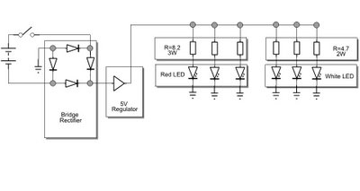
The white LEDs have varying voltage and current requirements, necessitating the use of different resistors. A parts list will be provided. The design concept is similar to previous iterations, but the white LEDs are configured differently due to their...

The transistors VTi, VT3, and VTs, along with the RC components, form three distinct multi-resonator oscillators. The oscillation frequency levels are dependent on the values of Ri, R3, Rs, and Cl, as well as Cz and C3s. The circuit comprises...

Getting microprocessor designs to function correctly is often challenging, particularly when both the software and hardware are unfamiliar. The typical method involves executing test routines that target memory and I/O without relying on their proper operation. However, any miswiring...

An astable oscillator is constructed using a 555 timer, producing an alarm tone of 1.8 kHz that directly drives a speaker. This fundamental alarm circuit serves as a basis for various other projects in the book. Although the circuit...
Warning: include(partials/cookie-banner.php): Failed to open stream: Permission denied in /var/www/html/nextgr/view-circuit.php on line 713
Warning: include(): Failed opening 'partials/cookie-banner.php' for inclusion (include_path='.:/usr/share/php') in /var/www/html/nextgr/view-circuit.php on line 713