
Car Speed Alarm Schematic
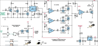
The Car Speed Alarm circuit is an essential tool for enhancing driving safety by providing audible alerts when speed limits are exceeded. The design incorporates several key components that work together to achieve this goal. The heart of the circuit is the LM2917 frequency-to-voltage converter, which accurately translates the frequency of speed pulses into a proportional voltage. This voltage is then compared against preset thresholds established by the adjustable trimpots, allowing for customization according to local speed limits.
The use of comparators allows for multi-threshold detection, enabling the circuit to provide distinct alerts for different speed ranges. The SCRs serve as electronic switches that activate the buzzer, ensuring that the alerts are both timely and effective. The RC networks are critical for filtering and smoothing the signals, preventing false alarms and ensuring reliable operation.
The piezo buzzer chosen for this application is effective in producing clear, audible tones that can be heard over road noise, making it an ideal choice for automotive applications. The design's flexibility, including the ability to set multiple speed thresholds, offers a user-friendly approach to speed monitoring without the need for constant adjustments.
Overall, the Car Speed Alarm circuit exemplifies a practical application of electronic components in enhancing vehicle safety, promoting responsible driving habits, and reducing the likelihood of speed-related accidents.When we are driving sometimes we do not know the speed of our car, especially when we are in the course of the highway so nice and straight, if the cars speed is too fast or faster than anyone could lead to accidents that do not want to happen. The circuit then requires the Car Speed Alarm is to alert the driver who did not notice the speed becaus
e the roads are nice and straight. Even this series can be set speed, for example, we set when exceeded 100km/h the alarm should sound. The workings of the circuit:A piezo buzzer will sound. Speed pulse is inserted into the base of Q1 and the resulting waveform at the collector is fed through a RC network to the input of an LM2917 frequency to voltage converter, IC1. The resulting voltage is fed to three comparators (IC2d-IC2b) which has a reference voltage at the inverting input they are set by the 10-turn trimpots VR1, VR2 and VR3.
The output of each comparator is applied through another RC network to the gate of an SCR. Anode of the three SCRs are commoned comparator inverting input connected to the left, IC2a. Non-inverting input is set to 2. 3 V with a trimpot VR4. In use, once you exceed the speed setting for the comparator in particular, relating SCR to briefly pull the pin 2 of IC2a low and short beep is emitted by a piezo buzzer. Then, if you exceed the speed setting that followed, another beep will be heard. The idea is to make each setting speed of several km / h higher than it actually is, so if you are driving at the correct speed in a particular zone, the buzzer will not sound.
But as you increase speed, the buzzer will beep once because you exceed the speed settings for each zone. In this way, there is no need to constantly switch setting the pace as you pass through different zones and you can choose to ignore the beep is not "illegal".
🔗 External reference
Related Circuits

Figure 3-118 illustrates an automatic acceleration control circuit. This circuit employs a male contactor time relay, enabling the motor to start automatically at a low speed before transitioning to high-speed operation. The automatic acceleration control circuit depicted in Figure 3-118...
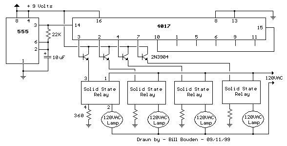
This circuit is basically the same as the 10 channel LED sequencer with the addition of solid state relays to control the AC lamps. The relay shown in the diagram is a Radio Shack 3 amp unit (part no....
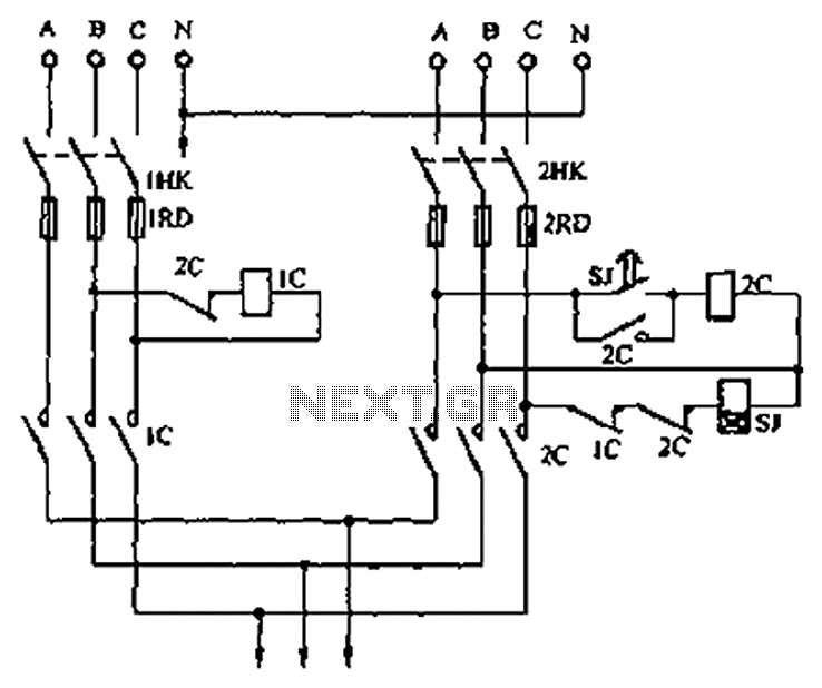
A dual three-phase power line circuit is illustrated in the figure. When the knife switches 1HK and 2HK are closed simultaneously, the normally closed contact 1C disconnects the power supply to the time relay SJ, allowing power to reach...
Simple Burglar Alarm / Door Alarm Circuit Diagram. This project can be utilized to secure a door or window. It emits a loud beep and activates the room light when an intruder attempts to break the door lock. The Simple...

This design is based on a publication by Milan Lulic in the German magazine elektroModell. Lulic's design utilizes surface mount technology (SMT), while this version employs standard off-the-shelf components, making it more accessible for hobbyists. For those interested in...
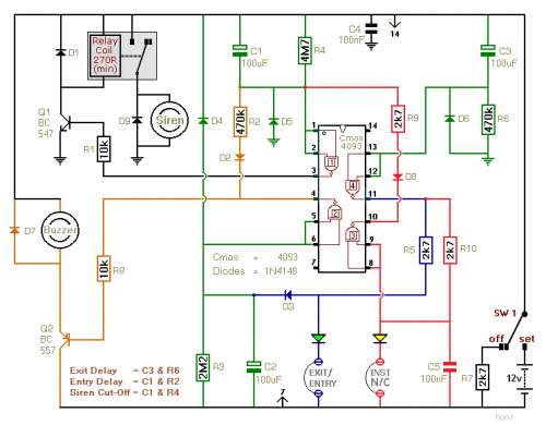
This two-zone alarm features automatic exit, entry, and siren cut-off timers. It was developed for the Beginner's Guide to CMOS Timers, providing a particularly detailed circuit description. An optional One-Time-Only module is available, which will deactivate the siren after...