
Car Voltmeter Circuit
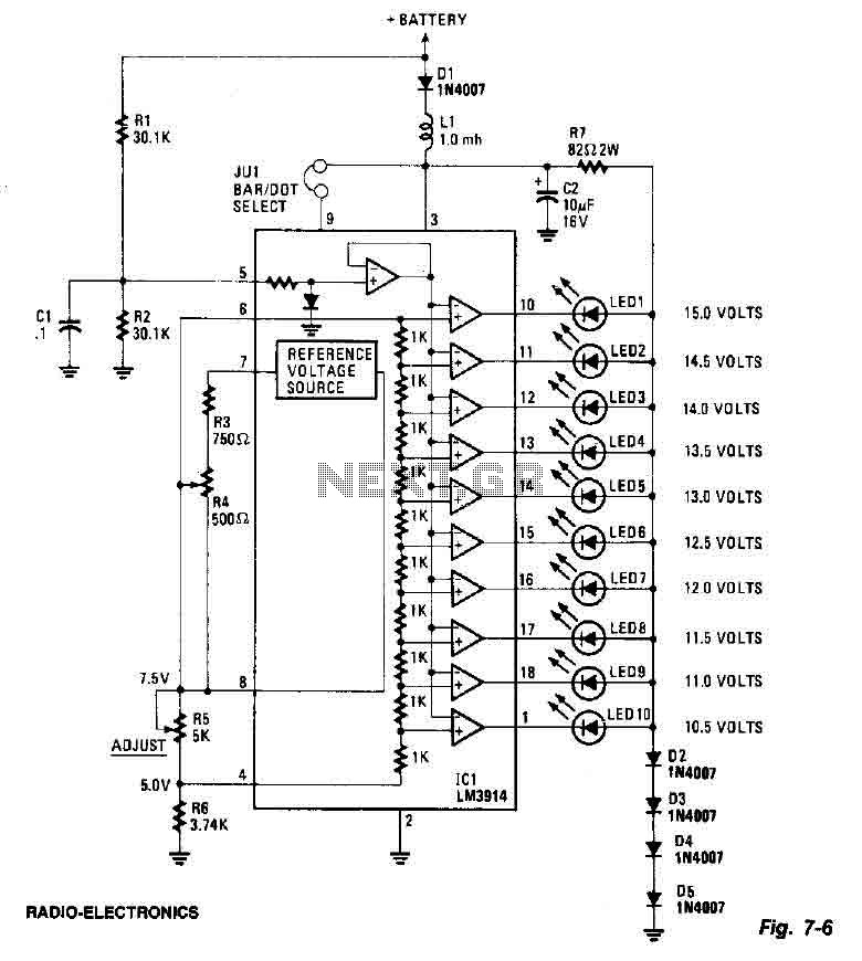
The circuit design features a series of ten LEDs arranged to provide a visual representation of the measured voltage level. Each LED illuminates sequentially for each 0.5-volt increment, allowing for an intuitive display of the voltage range. The LM3914 driver is specifically chosen for its ability to drive multiple LEDs in a linear fashion, ensuring accurate representation of voltage levels.
The trimming potentiometer R5 is an essential component, as it allows for calibration of the circuit. By adjusting R5, the voltage reference point can be set to 7.5 volts, which is critical for ensuring that the display accurately reflects the input voltage range. This adjustment helps maintain the linearity of the LED display.
Resistor R7, in conjunction with diode D5, plays a crucial role in regulating the voltage supplied to the LEDs. By ensuring that the voltage does not exceed 3 volts, this configuration protects the LEDs from potential damage due to overvoltage conditions. The use of a low-pass filter, consisting of inductor L1 and capacitor C2, is implemented to smooth out any voltage spikes that may occur in the circuit, thereby enhancing the reliability of the voltage readings displayed.
Furthermore, diode D1 is included in the design as a protective measure against reverse polarity connections. This diode ensures that if the voltmeter is connected in reverse, it will prevent damage to the circuit by blocking any reverse voltage from affecting sensitive components.
Overall, this circuit provides a robust solution for visual voltage monitoring, utilizing a well-thought-out arrangement of components to ensure accuracy, safety, and durability in operation.This screen uses ten LEDs to display a voltage range of 10.5 to 15 volts. Each LED represents a step 0.5wvolt tension. The heart of the circuit is the 3914 points LM / bar display driver. Trimming potentiometer R5 is adjusted so that 7.5 volts is applied to the upper side of the bulkhead. D2 resistor R7 and diode D5 to tighten the voltage applied to the LED 3 volts. A lowpass filter consisting of L1 and C2 guards against voltage spikes. The diode D1 is used to protect against reverse voltage where the voltmeter is connected backwards. 🔗 External reference
Related Circuits
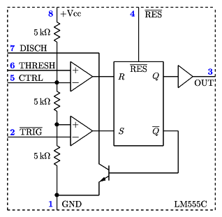
It is a typical Astable Multivibrator (AMV) setup. The capacitor charges through both resistors until it reaches 2/3 of Vcc, which is the level of the internal comparator. This triggers a flip-flop, activating the Discharge output (DIS). The capacitor...

This approach utilizes a Hip-Hop, a shift register, and two gates (A). Before the one-shot pulse, the output of the NOR gate is 0. Consequently, the data input of the D-type flip-flop is equivalent to the trigger. When a...
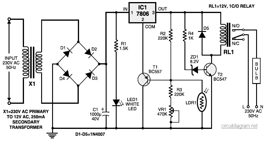
During nighttime, when no light falls on LDR1, it offers a high resistance at the base junction of transistor T1. Consequently, the bias is significantly reduced, and T1 does not conduct. This effectively removes the common terminal of IC1...
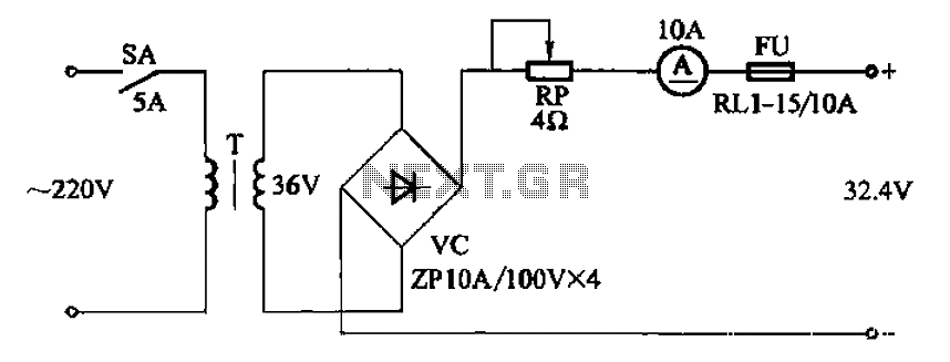
The adjustment potentiometer RP can modify the charging current. The adjustment potentiometer, designated as RP, serves a critical role in regulating the charging current within an electronic circuit. This component is typically a variable resistor that allows for fine-tuning of...
An operational amplifier designed for medium power applications, utilized as a headphone amplifier capable of driving low loads. The circuit consists of two amplifiers, with a voltage gain set at 40 dB, determined by the resistor pairs R3-R4 and...
The circuit was taken from an old Elektor electronics magazine and is a compact design suitable for generating high-intensity lighting effects during festivals, parties, and gatherings. Diodes D1 and D2, along with capacitors C1 and C2, form a voltage...