
L200 12V Constant Voltage Battery Charger Circuit

The L200 constant voltage battery charger circuit is designed to provide a stable 12V output for charging batteries. The core component of this circuit is the L200 voltage regulator, which is known for its ability to maintain a consistent output voltage despite variations in input voltage and load conditions.
The circuit typically includes the following components:
1. **Input Voltage Source**: This is the power supply that feeds the circuit. It must provide a voltage higher than 12V to ensure proper regulation by the L200.
2. **L200 Voltage Regulator**: The L200 is a versatile adjustable voltage regulator with five pins: input, output, ground, and two adjustment pins. The output voltage can be set using external resistors connected to the adjustment pins, allowing for precise control over the output voltage.
3. **Filtering Capacitors**: Input and output capacitors are used to smooth out the voltage and reduce ripple. These capacitors are critical for maintaining a stable output voltage and protecting the circuit from noise.
4. **Current Limiting Resistor**: To prevent excessive current from flowing into the battery during charging, a current limiting resistor may be included in the circuit. This component ensures that the charging current remains within safe limits for the battery being charged.
5. **Diode**: A diode may be placed in parallel with the output to prevent reverse current flow when the charger is disconnected from the battery. This protects the circuit and battery from potential damage.
6. **Heat Sink**: Depending on the load and input voltage, the L200 may require a heat sink to dissipate excess heat generated during operation, ensuring reliable performance.
The circuit can be assembled on a printed circuit board (PCB) for compactness and reliability. It is essential to consider the specifications of the battery being charged, including its voltage and capacity, to select appropriate components and ensure safe operation.
Overall, the L200 12V constant voltage battery charger circuit is an effective solution for charging lead-acid or similar batteries, providing a reliable and adjustable charging mechanism.L200 12V Constant Voltage Battery Charger Circuit This battery charger is based on L200 regulator IC. L200 is a five pin adjustable voltage and.. 🔗 External reference
Related Circuits
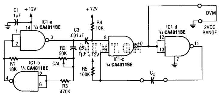
This circuit is designed for capacitor matching applications. The DC output voltage is directly related to the capacitance values of capacitor Cx. The specified circuit values are intended for capacitors in the 0.01 microfarad range; however, they can be...
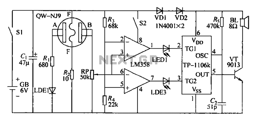
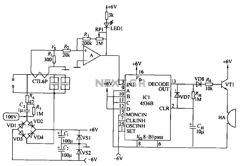
Car drivers and motorcyclists, despite prohibitions against drinking and driving, may still engage in this dangerous behavior. In such cases, the circuit can detect the presence of alcohol. If alcohol is detected, a warning message is issued immediately. If...
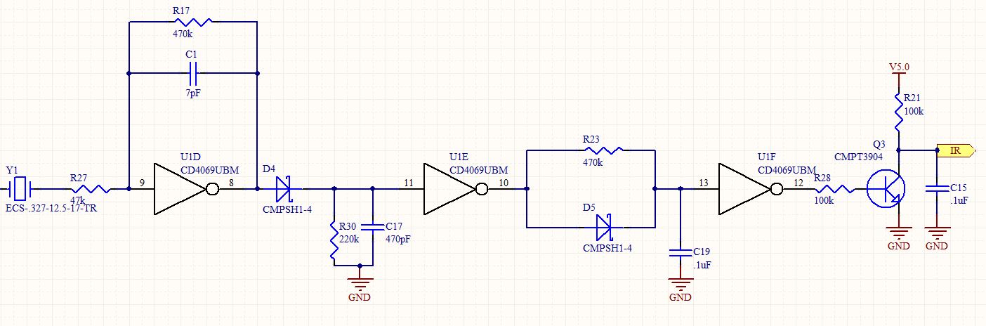
This is a follow-up to an earlier post regarding a specific circuit schematic. The circuit is designed to operate at a supply voltage of 5V, and testing has confirmed that the original device functions correctly at this voltage. A...
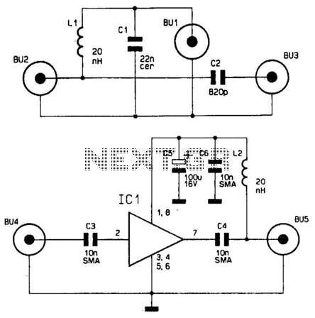
This wideband antenna preamplifier has a gain of approximately 20 dB from 40 to 860 MHz, covering the entire VHF, FM, commercial, and UHF bands. A phantom power supply delivers DC power to the preamplifier through the coaxial cable...
The circuit principle involves using a current transformer for current sensing due to the large AC power load of computers. This setup detects whether there is current in the power line, enabling the determination of its status. The LM393...
C1 filters the noise and spikes from the AC supply. The circuit can be adjusted to provide a 9V or 12V output voltage, or any other voltage level required by the PC mini drill, using the P1 potentiometer. The circuit...