
Carrier-Operated Relay

The COR/CAS circuit serves as a crucial component in repeater systems, allowing for effective signal management and relay control. The silicon diode CR1 functions as a rectifier, ensuring that only the appropriate current flows through the circuit, protecting sensitive components from reverse voltage. The choice of relay 2, preferably a reed relay, enhances the reliability and longevity of the circuit due to its low power consumption and minimal wear over time.
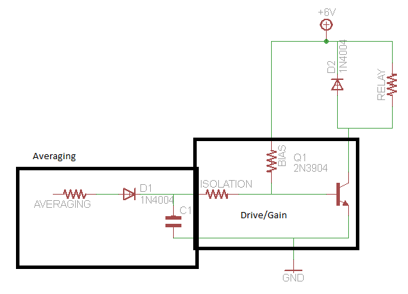
The timing aspect of the circuit is facilitated by resistor R2 and capacitor C1, which together form an RC timing network. The values of R1 and C1 are critical in determining the timing interval, with the configuration allowing for adjustments to achieve a hang time of up to four minutes. The use of a low-leakage capacitor for C1 is paramount, as it minimizes the loss of charge, thereby ensuring accurate timing and reliable operation.
The silicon-controlled rectifier Q1 plays a vital role in controlling the relay K1. When triggered, Q1 allows current to flow through the relay coil, energizing it and closing the contacts. The choice of a miniature relay with a 12-volt coil for K1 ensures compatibility with the circuit's power supply while maintaining a compact design.
The reset functionality of the timer is designed to be sensitive to supply voltage interruptions. This feature is essential for maintaining the integrity of the repeater operation, as it allows for automatic reset conditions after temporary power loss. The remote reset capability is an added benefit, enabling external control over the timer function, provided that the switch remains in the reset position.
Overall, this COR/CAS circuit is engineered for efficiency and reliability in repeater applications, integrating essential components that work in harmony to achieve desired operational outcomes. The inclusion of a delay circuit ensures that the relay remains engaged for a defined period following signal loss, contributing to the overall robustness of the repeater system. A shows a COR/CAS circuit for repeater use. CR1 is a silicon diode. 2 may be any relay with a 12-V coil (a long-life reed relay is best). R2 sets the length of time that K2 remains closed after the input voltage disappears (hang time). shows a timer circuit. Values shown for Rl and CI should provide timing up to four minutes or so. CI should be a low-leakage capacitor; Ql is a silicon-controlled rectifier, ECG-5452 or equivalent. Kl may be any miniature relay with a 12-volt coil. The timer is reset when the supply voltage is momentarily interrupted. The switch must be in the reset position for the remote reset to work. This circuit operates from the detector output of a receiver. A delay circuit is included so that the relay stays closed for a time period after the carrier output from the receiver disappears.
Related Circuits
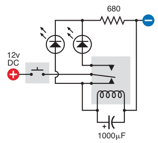
The intended result is for the relay to oscillate and the LEDs to flash when the button is pressed. However, when the button is pressed, the leftmost LED lights constantly, and nothing else happens. There is voltage across the...
This circuit demonstrates that microprocessors, PCs, and modern ultra-accurate Digital-to-Analog Converters (DACs) are excessive for controlling four relays in sequence based on a control voltage ranging from 2.4 V to 12 V. By utilizing equal resistors in a ladder...

A relay is an electromechanical switch that operates by opening and closing under the control of another electric circuit. When current flows through the relay's coil, a magnetic field is generated, causing an armature to move, which either establishes...
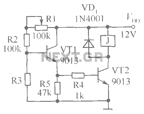
This document presents a brightness control relay circuit. Resistors R1, R2, and R3 create a voltage divider circuit with a light-sensitive resistor. When the light level drops below a specific threshold, the base voltage of VT1 increases, causing VT1...
A simple thermostat circuit that can control a relay to supply power to a small space heater through the relay contacts. The relay contacts must be rated above the current requirements for the heater. Temperature changes are detected by...
A circuit that activates a relay upon detecting audio pulses from one channel of an MP3 player. The intention is to synchronize recorded audio pulses with music to control a motor for mouth movement. For a stereo player, music...