
Toy Motor Drivers
The circuit in question is a simple yet effective design that utilizes a single transistor to control the operation of a permanent magnet DC motor. The transistor acts as a switch, allowing current to flow to the motor when the base is activated. The choice of the 8050 or 8550 transistor is critical, as these components are specifically designed to handle the power and thermal characteristics necessary for motor applications. The distinction between the 625mW and 1W variants is significant; the 625mW version is typically employed in low-power applications, ensuring that the transistor operates within safe limits under normal conditions.
The circuit's design inherently limits the current flowing through the motor when it stalls, thanks to the VCEsat characteristic of the transistor. This feature is particularly advantageous in children's toys, where unintentional stalling can occur frequently. By preventing excessive current flow, the circuit protects the transistor from damage and prolongs the life of the battery, making it a reliable solution for toy manufacturers.
Transient suppression is another crucial aspect of this circuit. The ceramic capacitor placed across the motor terminals serves to dampen voltage spikes generated by the inductive load of the motor, which can otherwise lead to electrical noise and potential damage to the circuit. The choice of a filter capacitor across the power supply can vary based on the specific requirements of the motor and control circuitry, with electrolytic capacitors often providing better performance in terms of energy storage and filtering capabilities.
In summary, this one-transistor circuit serves as an efficient and reliable means of driving permanent magnet DC motors in children's toys, with careful consideration given to component selection, current limiting, and transient suppression to ensure optimal performance and longevity.This is an actual reverse engineered circuit diagram of the one transistor circuit most commonly used to drive Permanent Magnet DC motors in childrens` toys. This type of circuit almost always uses the 625mW version of the ubiquitous 8050 or 8550 transistor. It is vital to note that there are two different varieties of each of these two transistor s, and although they are often stamped with the same part number, they are not interchangeable because one is a 625mW part with a higher VCEsat, while the other is a 1W part with a lower VCEsat. This is very confusing because you often have to run tests on these transistors to tell them apart! The important feature to note about this circuit, is that the maximum power delivered to the motor is normally designed to be limited by the VCEsat of the transistor, and almost never by the HFE or base current.
This works beutifully for childrens toys which are designed around a 3 volt or 4. 5 volt power supply, because whenever the child stalls the motor, this natural current limiting prevents burnout of the transistor and also preserves the battery life. The critical importance of the prior statement can not be overstated. Please not also that the ceramic transient suppression capacitor is always soldered directly across the motor terminals, and note that the filter capacitor across the power supply is just as often a small electrolytic instead of a ceramic disk, depending on the motor transient supression requirements of the control circuitry.
🔗 External reference
Related Circuits
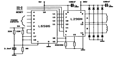
The following figure illustrates the control circuit for a two-phase bipolar stepper motor utilizing the current controller L6506. The L6506 integrated circuit generates the necessary signals to drive the inputs of the L298 bipolar stepper motor circuit driver. The circuit...
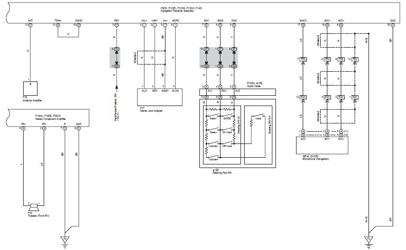
This document contains the wiring diagram for the 2007 Toyota Camry, specifically for the GSV40 and ACV40 series. It details the electrical circuits present in the vehicles, categorizing them by system for clarity. The wiring for each system is...

An innovative current detection method eliminates the power loss associated with the sense resistor in series with the motor. A 4-digit analog converter (DAC) facilitates digital control of the motor current path, simplifying the implementation of full, half, and...
A circuit that will find enough applications. Basically, the designing became in order to exist delay in quench one or more lamps in a stairwell or in any other space exists this need. It can become use for the...
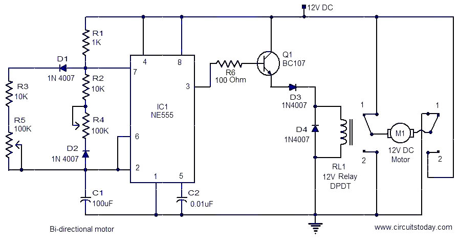
This is a simple and easy-to-construct circuit designed to provide a bidirectional drive for a DC motor. The circuit operates straightforwardly. The output of an astable multivibrator based on IC1 (NE555) is utilized to control the relay RL1 that...
Constructing a robot, or rather a vehicle, that uses two motors. Reference materials regarding the schematics for the circuit design have been obtained, but the current schematics utilize smaller motors that draw less power and operate with a lower...