
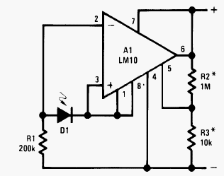
LM10 Current Regulator

A current regulator circuit is designed to ensure that a specific current flows through a load, providing stability in applications where current fluctuations could lead to undesirable performance or damage. The circuit typically consists of an operational amplifier (op-amp), a reference voltage source, and a pass element such as a transistor or MOSFET.
In operation, the op-amp compares the voltage across a sensing resistor, which is in series with the load, to a predetermined reference voltage. When the load current increases and the voltage across the sensing resistor exceeds the reference voltage, the op-amp's output will adjust the gate or base of the pass element, reducing the current flow to maintain the desired output. Conversely, if the load current decreases, the op-amp will increase the output to allow more current to flow.
This feedback mechanism allows the current regulator to adapt to changes in load conditions while ensuring that the current remains stable. The design can be applied in various scenarios, including LED drivers, battery chargers, and precision current sources in laboratory settings. Proper selection of components, including the op-amp, pass element, and sensing resistor, is crucial for achieving the desired performance and stability in the current regulation process.Current regulator acts like a load when connected to a voltage source, or in series between voltage source and real load. The main characteristic of a current.. 🔗 External reference
Related Circuits
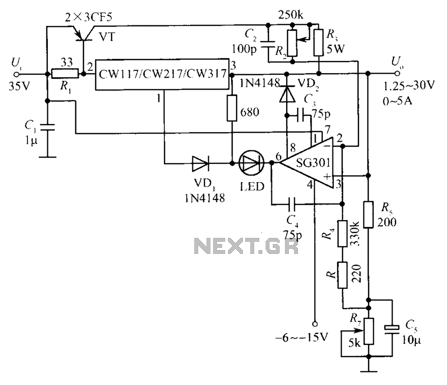
This document presents a diagram of a constant voltage/current power supply box. It is composed of three main components: spread current, constant voltage, and constant current. The design features two 3CF5 power transistors arranged in parallel, functioning as an...
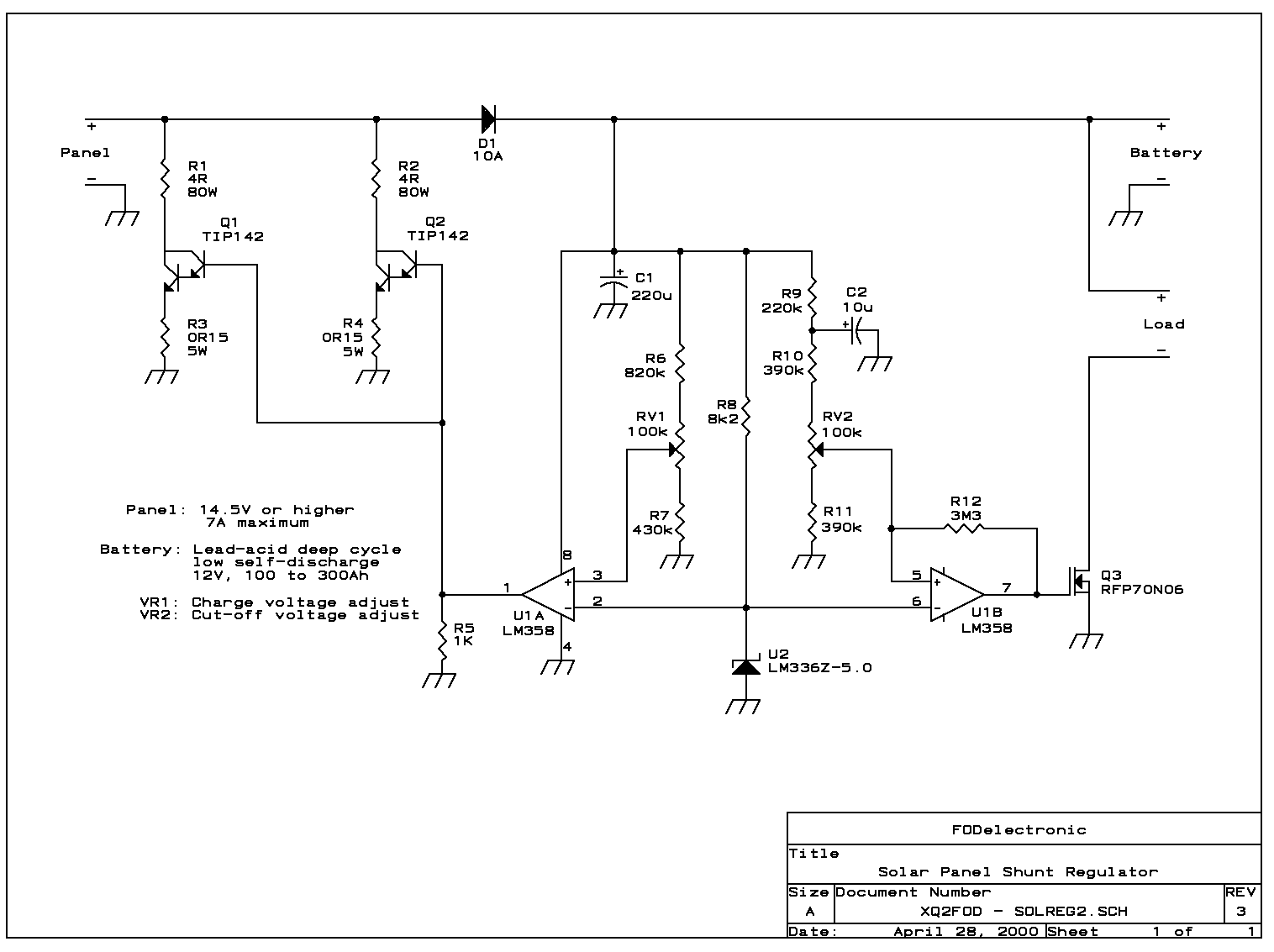
The circuit presented here uses linear shunt regulation. Simply spoken, it burns off all excess energy from the panel, keeping output voltage constant. At times when the solar panel output is equal or greater than the load, and the...
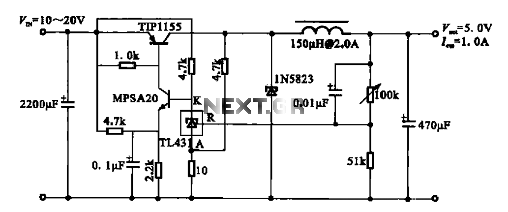
The 5V regulator circuit is designed to convert a DC input voltage ranging from 10V to 20V into a stable 5V output. This circuit features low power consumption and high efficiency. The 5V regulator circuit typically employs a linear voltage...
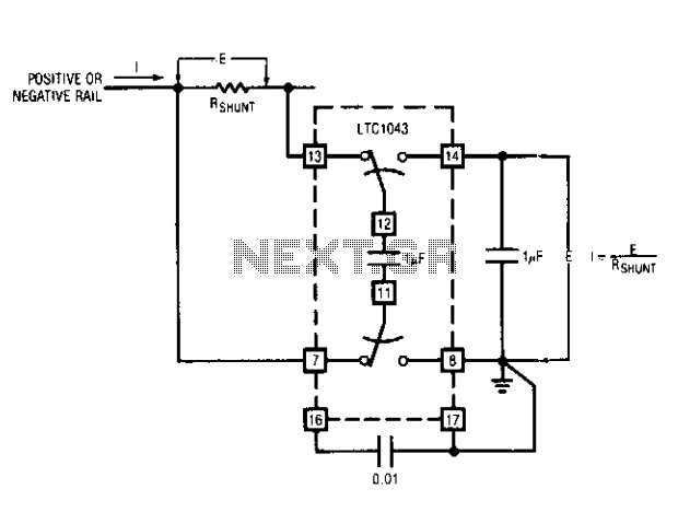
This capability has wide application in battery and solar-powered systems. If the ground-referred voltage output is unloaded by an amplifier, the shunt can operate with very little voltage drop across it, minimizing losses. The LTC1043 can sense current through...
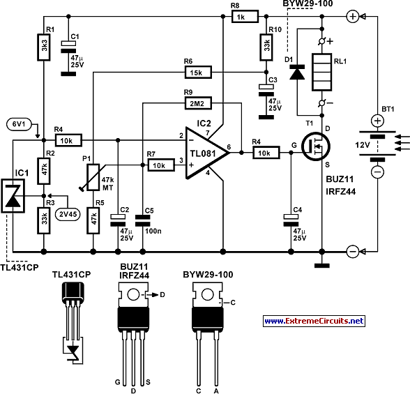
The design of solar panel systems with a lead-acid buffer battery typically allows for battery charging even during low sunlight conditions. However, this necessitates the use of a regulator to prevent overcharging during periods of abundant sunshine. Common solutions...
This circuit is a two-wire light level detector, which does not separate the wires for power supply and output signal delivery. It operates using a current loop that performs both functions over a single pair of cables, requiring only...