
Celsius Thermometer
The LM334 integrated circuit serves as a versatile temperature sensor, utilizing a current output that varies linearly with temperature changes. The configuration of the sensor for 1 µA per Kelvin is achieved through precise adjustments with potentiometers, ensuring that the output aligns with practical temperature measurements in degrees Celsius. The use of a 2.5 V reference voltage from IC2 stabilizes the circuit, providing a reliable baseline for the current readings.
The calibration procedure outlined is critical for achieving accurate temperature readings. By initially short-circuiting IC2, the adjustment of P1 allows for a direct correlation between the sensor output and the ambient temperature, compensating for the inherent offset of the LM334. This step is essential for establishing a reliable zero point in the measurement system.
Once the initial calibration is complete, the removal of the short-circuit on IC2 and the subsequent adjustment of P2 fine-tunes the output to reflect the actual room temperature. This two-step calibration ensures that the system is not only accurate but also user-friendly, as it can be easily adjusted against a standard thermometer.
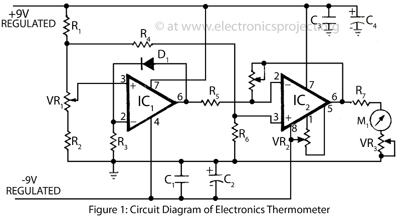
The low current draw of the circuit enhances its practicality in battery-powered applications, as it allows for extended operational life with standard AA batteries. This feature makes the Celsius thermometer circuit ideal for portable or remote temperature monitoring applications, where long-term reliability is a key requirement. Overall, this circuit design exemplifies an efficient approach to temperature measurement, combining simplicity with accuracy and longevity.The circuit of the Celsius thermometer in the diagram is based on the well-known Type LM334 from National Semiconductor. This IC is a sensor that provides a current which is directly proportional to the temperature in kelvin (K).
Unfortunately, this is a quantity that is not suitable for use in most practical applications. In the circuit, therefor e, the sensor is set to 1 µA K 1 with P1 and the offset of 273 K removed with P2. This renders the output voltage of the sensor directly proportional to the temperature in degrees Celsius ( ° C) and this makes the circuit suitable for a great many applications (since 1K=1 ° C). Circuit IC2 is arranged as a 2. 5 V reference voltage source. The current setting of the sensor is determined by the resistance between the adj(ust) pin and earth.
If the earth is made virtual by raising the potential at the adj pin, the zero point can be shifted as desired. Calibration is best done by using a good domestic thermometer as reference. Start by short-circuiting IC2 and adjusting P1 until the reading of meter M1 shows a current value numerically equal to the ambient temperature plus 273.
If, say, the room temperature is 25 °C, adjust P1 until the meter reads 298 µA. Then, remove the short-circuit from IC2 and adjust P2 until the meter reads a current whose numerical value is equal to the room temperature, that is, 25 µA. The circuit draws a current not exceeding 1mA, so using two AA size (AM3, MN1500, LR6, SP/HP7) batteries as power source will give a life of a couple of years.
🔗 External reference
Related Circuits
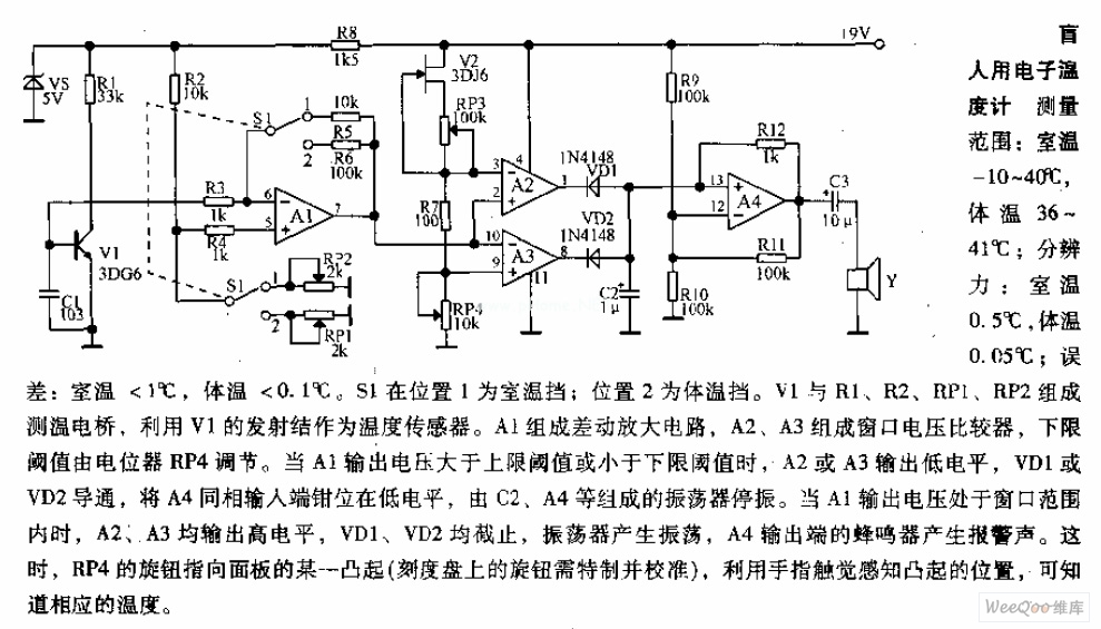
Measuring range: room temperature is -10 to 40 degrees Celsius; body temperature is 36 to 41 degrees Celsius; Resolution: room temperature is 0.5 degrees Celsius, body temperature is 0.05 degrees Celsius; error: room temperature <1 degree Celsius, body temperature <0.1 degrees Celsius. When switch S1 is in position 1, it displays the room temperature profile; position 2 displays the body temperature profile. Components V1, R1, R2, RP1, and RP2 form the temperature measurement circuit. The temperature measurement circuit is designed to monitor and display two distinct temperature ranges: ambient room temperature and body temperature. The circuit operates with a measuring range for room temperature from -10 to 40 degrees Celsius and for body temperature from 36 to 41 degrees Celsius. The resolution of the circuit is fine-tuned to provide accurate readings, with a room temperature resolution of 0.5 degrees Celsius and a body temperature resolution of 0.05 degrees Celsius. The specified error margins indicate a maximum deviation of less than 1 degree Celsius for room temperature measurements and less than 0.1 degrees Celsius for body temperature measurements. The circuit utilizes a switch, S1, which allows the user to select between the two temperature profiles. In position 1, the circuit outputs the room temperature, while in position 2, it outputs the body temperature. The operational components include a voltage source (V1), resistors (R1, R2), and potentiometers (RP1, RP2) that are integral to the measurement process. Resistors R1 and R2 are likely part of a voltage divider network that aids in scaling the temperature sensor output to a readable format. Potentiometers RP1 and RP2 can be used for calibration purposes, allowing fine adjustments to ensure that the readings are accurate within the specified error margins. The temperature sensor, which is not explicitly mentioned but is assumed to be part of the circuit, converts temperature changes into an electrical signal that can be processed by the circuit. The output from the sensor is conditioned by the resistive components to produce a voltage level that corresponds directly to the measured temperature. This voltage is then displayed on an appropriate display unit, which could be an analog gauge or a digital readout, depending on the design of the circuit. Overall, this temperature measurement circuit is a practical solution for monitoring both ambient and body temperatures with high accuracy and user-friendly operation through the selection switch.

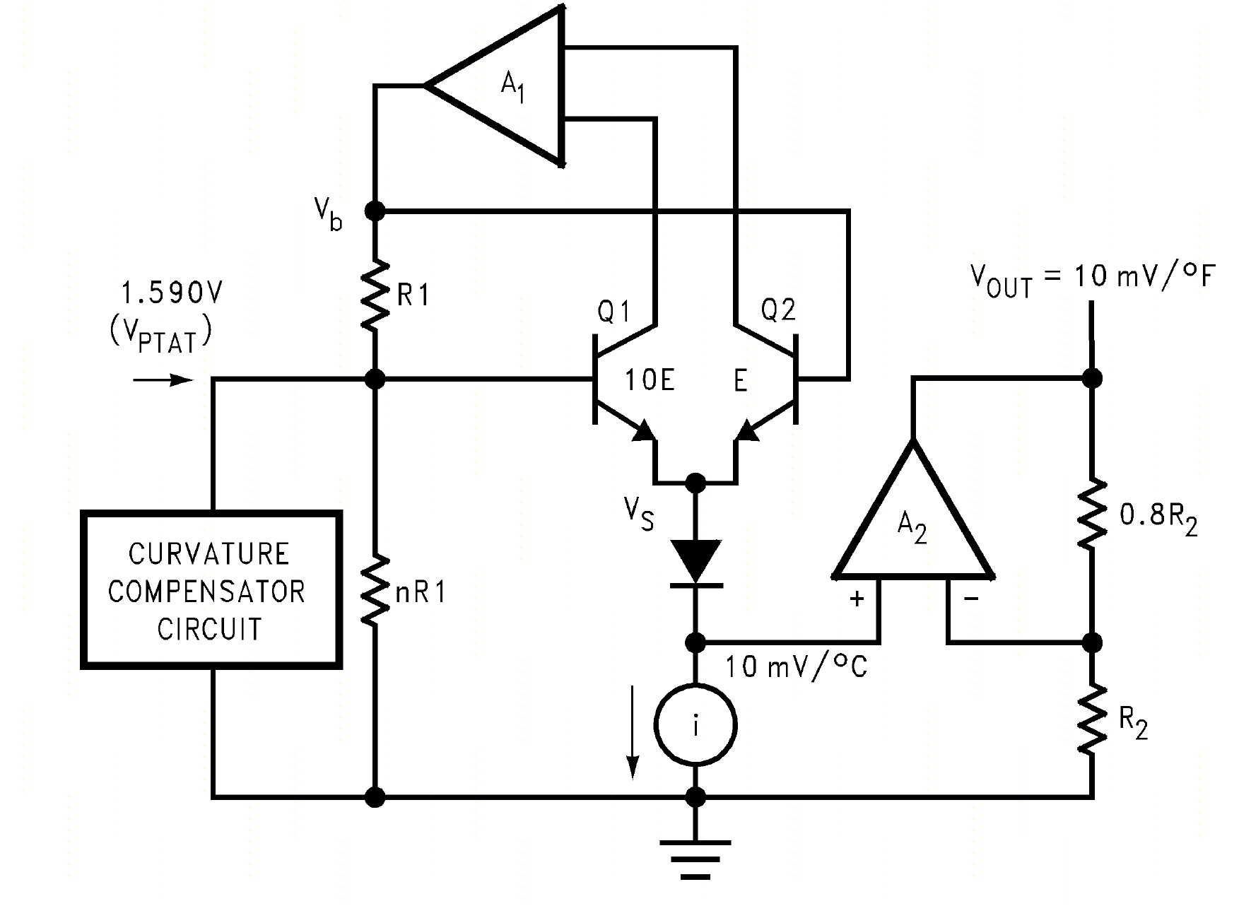
The schematic diagram described here is a TMP01 Celsius Scale Temperature Sensor circuit. This circuit is used to convert the VPTAT output voltage. The TMP01 is a temperature sensor integrated circuit designed to provide an accurate temperature measurement in Celsius....
The availability of affordable digital multimeters and integrated circuit temperature sensors has made it straightforward to create a sensitive and accurate digital thermometer suitable for various experiments at home or in amateur laboratories. Two temperature sensors that simplify this...
A highly accurate digital thermometer utilizing an LM35 probe with a resolution of 0.1 degrees Celsius. The circuit includes two adjustable components. The first, R5, is used to calibrate the display to zero. To perform this calibration, the end...

This digital thermocouple thermometer utilizes one active component and 15 passive components. The circuit is compatible with both type J and type K thermocouples. The type J thermocouple measures temperatures ranging from 10 to 530 °C with an accuracy...
A clinical thermometer is typically used by doctors due to its complex reading mechanism. This circuit represents an electronic thermometer designed to measure a wide temperature range from -200°C to 1250°C. This single circuit electronic thermometer is capable of...