
TMP01 Celsius Scale Temperature Sensor

The TMP01 is a temperature sensor integrated circuit designed to provide an accurate temperature measurement in Celsius. It operates by generating a voltage output proportional to the temperature, utilizing the VPTAT (Voltage Proportional to Absolute Temperature) output voltage. This output can be interfaced directly with analog-to-digital converters (ADCs) or microcontrollers for further processing and display.
The schematic typically includes the TMP01 IC, which has pins for power supply, ground, and output voltage. It requires a stable power supply, often in the range of 4V to 30V, depending on the specific model. The output voltage from the TMP01 is linearly proportional to the temperature in degrees Celsius; for example, it outputs 10 mV per degree Celsius.
In practical applications, the circuit may include additional components such as resistors for pull-up or pull-down configurations, capacitors for noise filtering, and possibly an operational amplifier to enhance the output signal for better resolution. The sensor can be employed in various applications, including HVAC systems, environmental monitoring, and industrial automation, where precise temperature measurements are crucial.
The layout of the circuit should ensure minimal interference from external noise sources, and proper grounding techniques should be utilized to maintain signal integrity. Overall, the TMP01 Celsius Scale Temperature Sensor circuit is a reliable solution for real-time temperature monitoring and control in various electronic systems.The schematic diagram described here is a TMP01 Celsius Scale Temperature Sensor circuit. This circuit is used to convert the VPTAT output voltage that is . 🔗 External reference
Related Circuits
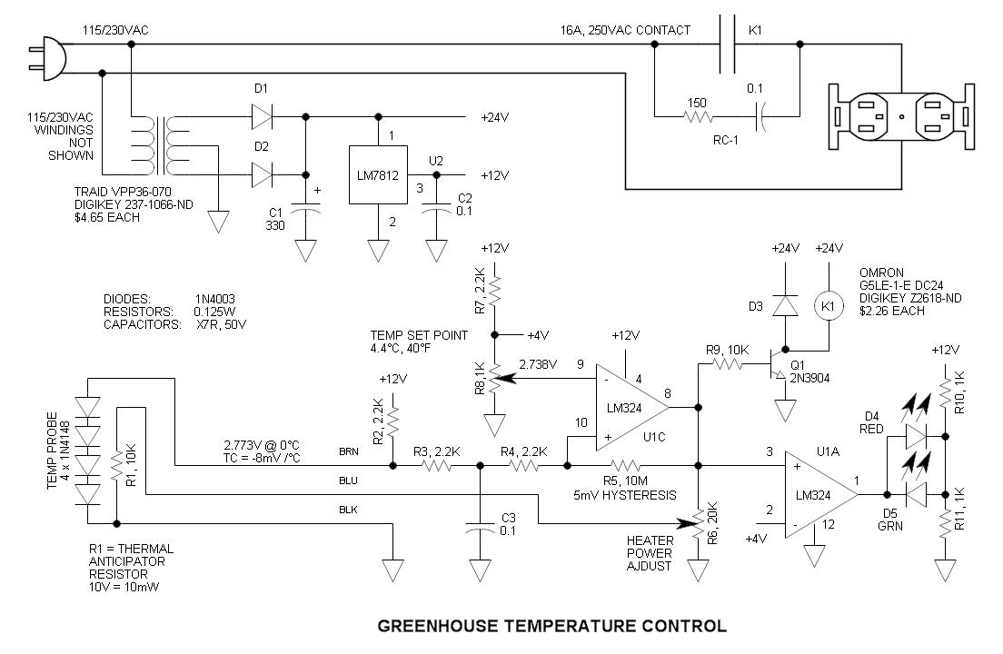
This circuit consists of four 1N4148 diodes connected in series with a thermal anticipation resistor (R1) heat-shrunk together at the end of a three-wire signal cable, which is visible in some photos. The thermal anticipation resistor is an old...

Figure 4-52 (a) illustrates the two-phase wiring for direct current (DC) operation, while Figure 4-52 (b) depicts the two-phase current differential wiring for alternating current (AC) operation. The schematic in Figure 4-52 (a) represents a two-phase wiring configuration suitable for...

555 precision temperature sensor with temperature frequency converting circuit diagram consisting of: The 555 precision temperature sensor operates by converting temperature variations into frequency signals. This circuit typically utilizes a 555 timer IC configured in astable mode to generate...
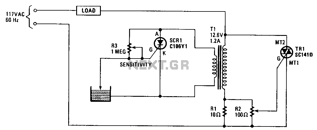
When the water level is low, the probe is out of the water, causing SCR1 to be triggered. This results in the SCR conducting and imposing a significant load on the secondary winding of transformer T1. This load is...
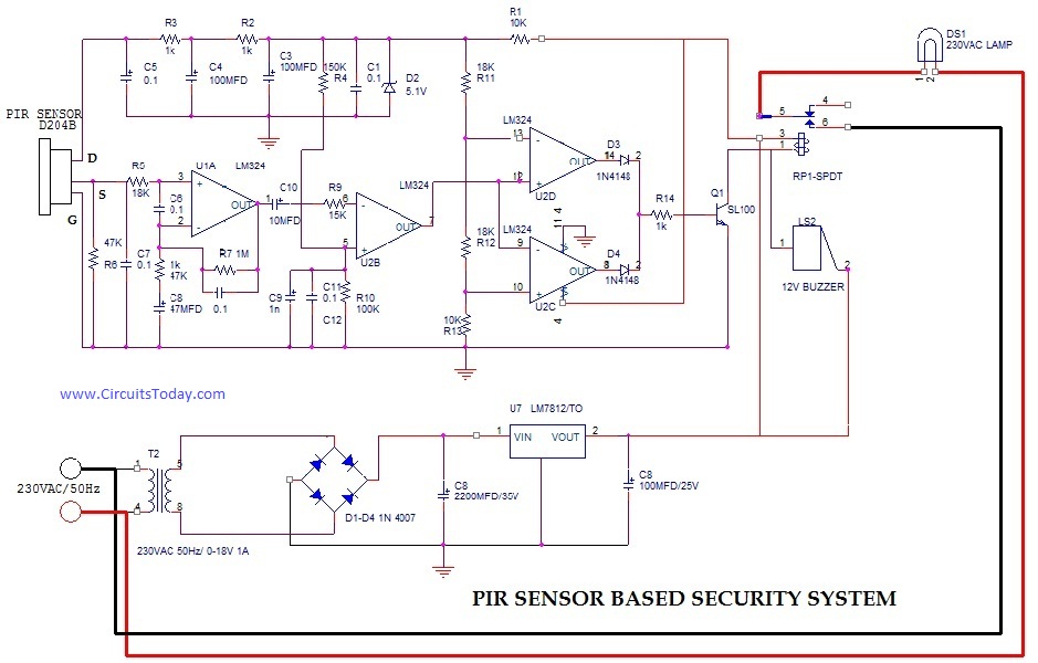
PIR (Passive Infrared Radial) Sensor-Based Security System, circuit diagram, working, applications. The PIR (Passive Infrared) sensor-based security system is designed to detect motion by measuring changes in infrared radiation emitted by objects in its vicinity, particularly warm bodies such as...
The purpose of this circuit is to animate shop windows using a capacitive sensor positioned behind a postcard-like banner. The card is placed against the glass inside the shop window, allowing visitors to activate the relay by placing their...
Warning: include(partials/cookie-banner.php): Failed to open stream: Permission denied in /var/www/html/nextgr/view-circuit.php on line 713
Warning: include(): Failed opening 'partials/cookie-banner.php' for inclusion (include_path='.:/usr/share/php') in /var/www/html/nextgr/view-circuit.php on line 713