
CGA to SCART Adapter
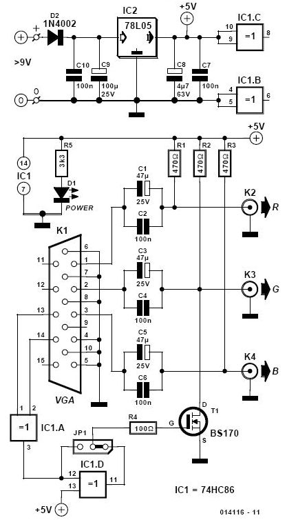
The CGA to SCART adapter circuit is designed to accommodate the video signal conversion requirements between CGA (Color Graphics Adapter) and SCART (Syndicat des Constructeurs d'Appareils Radiorécepteurs et de Télévision) standards. The circuit primarily utilizes resistive voltage dividers to adjust the signal levels appropriately. The resistors R4, R5, and R6 are crucial in transforming the TTL-level signals from the CGA output to the required SCART levels, ensuring compatibility with the SCART input specifications.
The impedance matching is addressed through the configuration of these resistors, which, while not achieving an exact 75-ohm output, maintain signal integrity sufficiently for practical applications. The use of R1, R2, and R3 serves to modulate the brightness of the output signal, allowing for dynamic adjustment based on the state of pin 6. This feature enhances the adaptability of the adapter in various display scenarios, particularly when dealing with older CRT televisions that may not handle high brightness levels well.
Moreover, the synchronization aspect of the video signal is critical for proper display functionality. The circuit employs resistors R7 to R11 in conjunction with transistor T1 to combine the horizontal and vertical sync pulses from the CGA board, creating a composite sync signal. This signal is essential for synchronizing the display output with the video signal, ensuring that the image is rendered correctly on SCART-compatible televisions.
In summary, the CGA to SCART adapter is a compact and efficient solution for interfacing CGA video signals with SCART inputs, effectively managing signal levels, impedance, and synchronization to deliver a functional output suitable for a variety of display devices. The design emphasizes simplicity and effectiveness, making it an ideal choice for retro gaming and vintage computer applications.CGA to SCART adapter has great advantages as it does not require separate power source and that uses very few external components, which can be easily adapted in the SCART connector. The signals from R, G and B pins of the CGA`s board are converted from TTL levels to SCART levels with resistors R4, R5 and R6 and entry`s impedance (75 ©) of scart
inputs. Output Impedance of voltage dividers thus created is not exactly 75 © as specified for SCART inputs, but in practice the behavior seems to result not big differences. R1-R3 resistors from pin 6 of the CGA`s entrance and pins R, G and B of the SCART connector ensure reduction of 50% of brightness when pin 6 active.
From synchronization pulses on horizontal and vertical of CGA board it creates, with the help of R7-R11 ²s and T1, a composite signal timing (SYNC) and a signal remission for TV. 🔗 External reference
Related Circuits
There are monitors that feature only three BNC inputs and utilize composite synchronization (sync on green). This circuit has been specifically designed for such monitors. The design maintains simplicity while delivering reasonable performance. The operational principle is straightforward. The...
This really isn't much an electronics project as it is a telephone wiring project. Take note that this project involves connections to telephone lines. This may be frowned upon by your telephone service provider, AKA The Telephone Company. Always...
Diode D1 and resistor R1 provide VDD isolation during the programming of 24-pin devices. Jumper J3 must be shorted for 24-pin devices and left open for programming 28-pin devices. The following EEPROMs are pin compatible with their EPROM versions. In...
Measuring inductance is important for creating hand-made inductors, particularly when engaging in do-it-yourself (DIY) coil winding. An inductance meter adapter can facilitate this process. An inductance meter adapter is a vital tool for accurately measuring the inductance of coils and...
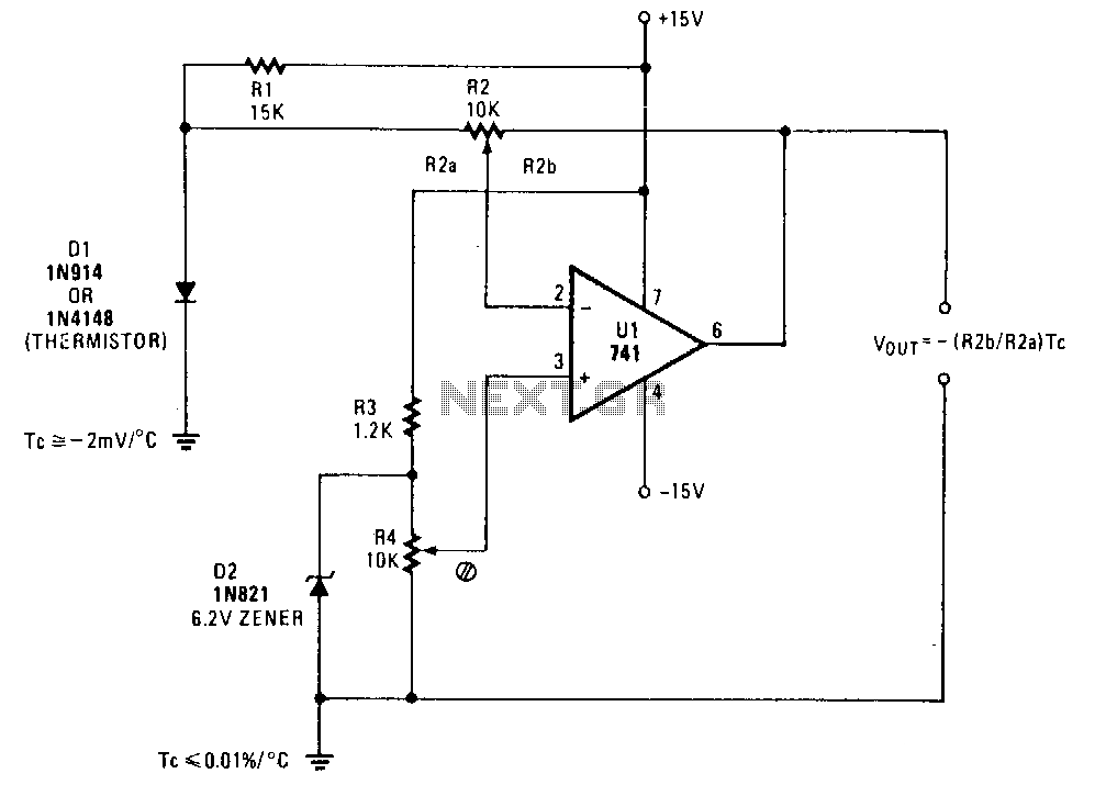
A simple operational amplifier and silicon diode form the core of a temperature-to-voltage converter, which allows the use of a standard voltmeter—either analog or digital—to measure temperature. User adjustments enable readings of either 10 mV or 100 mV to...
This project is currently under construction and has not been validated for functionality. A signal generator, resistor, and oscilloscope were utilized to measure the value of an inductor for a battery charger project. In the search for an affordable...
Warning: include(partials/cookie-banner.php): Failed to open stream: Permission denied in /var/www/html/nextgr/view-circuit.php on line 713
Warning: include(): Failed opening 'partials/cookie-banner.php' for inclusion (include_path='.:/usr/share/php') in /var/www/html/nextgr/view-circuit.php on line 713