
Light Bus speed detecting circuit diagrams
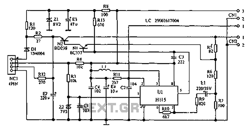
The minibus odometer circuit operates by utilizing a combination of electronic and mechanical systems to accurately measure and display vehicle speed and distance traveled. The pulse signals generated by the speed detection mechanism are crucial for the proper functioning of the odometer and speedometer. These pulse signals are typically produced by a sensor that detects the rotation of the vehicle's wheels or transmission output shaft.
Upon generation, the pulse signals are sent to the NC1 instrument cluster, which serves as the primary interface for the driver. The signals travel through the dash panel, where they are routed to the U1 electronic signal processing unit. This processing unit is responsible for interpreting the incoming pulse signals, converting them into meaningful data that reflects the vehicle's speed and distance.
The U1 unit employs various electronic components, such as microcontrollers or dedicated signal processing ICs, to analyze the frequency and duration of the received pulse signals. This data is then used to calculate the vehicle's speed in real-time, which is displayed on the speedometer. Additionally, the odometer function accumulates these signals over time to compute the total distance traveled, which is shown on the odometer display.
The final output is then transmitted to an electromagnetic meter, which uses electromagnetic induction principles to visually represent the speed and distance. This combination of electronic processing and mechanical display provides a reliable and efficient means for drivers to monitor their vehicle's performance. Overall, the integration of these systems results in a modern odometer that enhances the driving experience by providing accurate and real-time information. As shown below, is described in a minibus odometer circuits, the odometer and speedometer is electronic, mechanical integration combination of new instruments. Pulse signal out put from the locomotive speed detecting means, away from the NC1 instrument cluster, after the dash panel through to the core of U1 electronic signal processing system for processing, driving the electromagnetic meter shows mileage and speed.
Related Circuits

Basic features include an internal 512k-bit EEPROM, allowing for continuous recording and playback at any time, with long-term retention of voice data after power loss. The voice recording time is 20 seconds, and it supports segmented recording and playback....
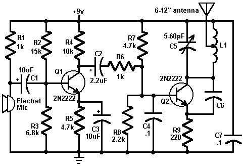
This circuit is a simple two-transistor (2N2222) mini FM transmitter. No authorization is required for this transmitter according to FCC regulations regarding wireless microphones. When powered by a 9-volt battery and equipped with an antenna no longer than 12...
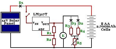
The circuit is designed to power a CCTV camera, provide lighting inside a nestbox, and charge batteries using a photovoltaic (PV) solar panel. It includes a circuit diagram for a solar-powered wireless CCTV camera with battery backup. D1 is...
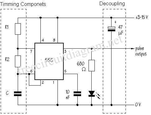
The SE555/NE555 timer was first introduced by the Signetics Corporation around 1971. Pin connections and functions are as follows: Pin 1 (Ground) - This pin serves as the ground or common pin, representing the most negative supply potential of...
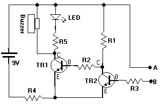
This document presents a water sensor circuit designed to monitor soil moisture levels for plants. This circuit is straightforward and is constructed using five resistors, two transistors, an LED, a buzzer, and a battery. The operation of the circuit...
The design of the combinational logic circuit is diverse. An example chosen for detailed explanation is the implementation of an even parity check circuit. The parity check circuit exhibits particular characteristics and practicality in the analysis and design of...