
pressure sensor circuit
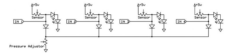
The design of the dance pad involves utilizing four pressure sensors arranged in a manner that corresponds to directional inputs: up, down, left, and right. Each sensor operates by detecting pressure applied to it, which changes its resistance. The goal is to create a system where a single variable resistor, or rheostat, serves as a pulldown for all four sensors. This allows for the adjustment of the sensitivity threshold, enabling the user to customize how much pressure is needed to register a button press.
In the intended design, when pressure is applied to a sensor, its resistance decreases, causing the corresponding input to register a high signal. Conversely, if the resistance is increased, the input should read low. The use of a common pulldown resistor simplifies the circuit and reduces component count, which is beneficial for both space and cost efficiency.
The schematic should reflect that each pressure sensor's output connects to the wiper terminal of the rheostat. This configuration allows for the voltage to be adjusted based on the pressure applied to the sensors. It is crucial to ensure that the correct wiring is followed to prevent all inputs from going high when one sensor is activated.
To achieve a reliable output, the circuit can be designed with pull-up resistors connected to the microcontroller's input pins. This configuration ensures that when no pressure is applied, the inputs are held high, and when a sensor is activated, the input is pulled low through the rheostat. The output from the sensors can be fed directly into a USB interface, allowing for straightforward integration with a computer or gaming system.
It is important to note that the system must be able to handle multiple simultaneous inputs, especially if multiple sensors are pressed at once. This may require additional circuitry or a more sophisticated microcontroller that can manage multiple digital inputs effectively.
In summary, a properly configured dance pad circuit will involve pressure sensors, a common pulldown rheostat, and a microcontroller capable of interpreting the binary outputs from the sensors. Careful attention to the schematic design and component selection will ensure the functionality and responsiveness of the dance pad.A dance pad, basically 4 pressure sensors (up, down, left, right). I already made the USB controller as a dance pad and whatnot, now I need to know how to hook up the actual sensors. I want the input to be pulled down to ground, so I figured that I would put a rheostat there as a variable resistor for the pulldown.
This way, I could adjust how strong the pull-down is, theoretically adjusting the amount of pressure required from the sensors. If the resistance is less in the sensor, then it should register a button press, whereas if the resistance is less through the pulldown, it should register a 0. That part all works just great, however, I want all of the sensors to use one pulldown adjustor, so I dont need to put 1 rheostat per sensor.
Attached is a schematic I thought would work, but in fact when I press a sensor, all of the inputs go high. What am I doing wrong EDIT: The schematic is drawn wrong. For all of those variable resistors, the outputs actually come off of the wiper, not the other side. I couldn`t find out how to do this in the schematic program, so I drew it like such to show the general idea.
All the resistors in the image are variable and set-up to be such. Actually, I cant use the AD converter beacuse there will be two pads at least and each should have its own pressure sensor. The way I did it, the outputs from the sensors can either go into USB, or can go out to another pad, which sends it to USB, so I need just simple 1 or 0`s I think I tried putting the adjustor pot on the 5volt source, adjusting the voltage.
Didnt really like how it worked, but maybe Ill mess around with that again, thanks. 🔗 External reference
Related Circuits
A circuit has been identified that integrates a voltage regulator and filter to isolate the voltage supplied by the receiver for powering an operational amplifier (op-amp) that drives a meter. Additionally, the circuit isolates the carrier frequency from the...
The following circuit illustrates the CD4017 integrated circuit (IC) used in an automatic room lights sensor circuit diagram. Features include a single light sensor utilizing two light-dependent resistors (LDRs). The CD4017 is a decade counter IC that can drive multiple...
Useful for checking transmitters and antennas, this circuit utilizes a voltage-doubling detector consisting of diodes D1 and D2, which can be HP 5082-2800 hot carrier types or alternatives such as 1N34 or IN82. The circuit incorporates a 100-mA meter...
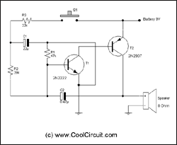
Siren Circuit. This circuit generates a sound siren when switch S1 is pressed, increasing the sound frequency as capacitor C1 charges. The sound frequency decreases when switch S1 is released. The siren circuit operates based on the charging and discharging...
A battery is a crucial component of any battery-backed system. Often, the battery is more costly than the system it supports. Therefore, it is essential to implement all practical measures to extend battery life. According to manufacturer data sheets,...
This circuit functions to monitor the duration of occupancy in a toilet, activating an alert if the time spent exceeds a predefined limit. The components involved include a resistor, integrated circuit (IC), capacitor, and transistor. The occupancy monitoring circuit is...