
Chizuru 100Hz channel frequency pulse charging electric bike battery circuit
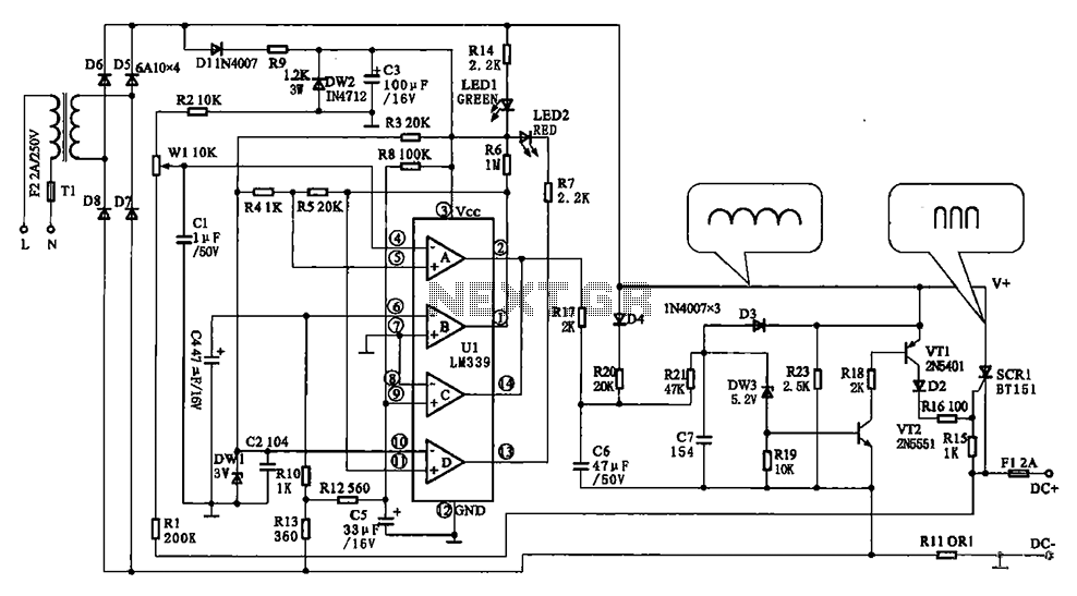
The Chizuru 100Hz pulse charging circuit is designed to efficiently charge electric bike batteries while ensuring safety and reliability. The step-down transformer (Tl) reduces the input voltage to a suitable level for battery charging. The bridge rectifier, composed of diodes D5 to D8, converts the AC output of the transformer into a pulsating DC current, which is critical for the charging process. The use of a thyristor (SCR1) as a charging switch allows for controlled charging cycles, where the SCR is turned on when the conditions are met, ensuring that the battery receives the correct voltage and current.
The circuit employs a feedback mechanism to monitor battery voltage and current, utilizing a combination of operational amplifiers and resistors. The battery voltage limiting circuit, which activates at 43.5V, is essential for preventing overcharging, a common issue in battery management systems. The current limit detection circuit ensures that charging is halted if the current exceeds a safe threshold, protecting both the battery and the circuit components from potential damage.
Additionally, the charging state detection circuit provides visual feedback through the LED indicator, allowing users to easily determine the charging status. This feature enhances user experience and ensures that the charging process is transparent. The overall design emphasizes safety, efficiency, and user-friendliness, making it suitable for electric bike applications. Chizuru 100Hz channel frequency pulse charging electric bike battery circuit Shown as Chizuru 1.00 I-Lz letter frequency pulse electric bicycle battery charging circuit. Freque ncy transformer Tl is a step-down transformer, D5 ~ D8 form a bridge rectifier, the output ripple current through Dl, R9, DW2 control circuitry. Way thyristor SCR1 is charging switch, which is turned on to charge the battery, since the power supply is shaped bread ioo Hz AaC move DC, zero crossing turn-off, so the charger 100 FIz pulse charger, the charging current waveform shown in Figure 2-77.
Charging switch is controlled by DW3, VT1, VT2, each cycle in bread shaped IOOH pulsating DC, v + potential rises to when DW3 reverse breakdown, v + through D4, R20, R21, DW3 make VT2 conduction, thereby enabling rri conduction, v + ~ vri, D2 make SCR1 is turned on when the battery voltage is higher than the potential v +, v + on the battery charge. However, if R20 and R2J dividing point grounding, v + another high potential, DW3, VI2, VI2, SCR1 is not turned on.
Protection circuit and charging stop is the use of the R20 and R21 dividing point potential to achieve low off the charge output. Battery voltage is detected by the pressure limiting UIA, Rl, Wl, R2 composition, when the battery voltage rises to 43.5V when, UIA flip, its feet on the ground conduction through R17 to R20 and R21 dividing point potential to achieve low close charging output.
Charge current limit is detected by the UIC, R12, R13 composition roar when the charging current exceeds the limit value, the current sampling resistor Rll left to reduce the potential to make UIC flip its feet on the ground! Conduction, the same will be R20 and R21 stars realize the potential of low pressure point off the charge output.
Charging state detected by the UIB, R10, R13 composition, the charge current exceeds a predetermined value, the current sampling resistor Rl1 potential drop left lower column UIB flip it O feet into high potential, prompting the charging status display driver UID flip it! pin potential becomes high, the charge lamp LED2 is off. O feet in potential UIB becomes high, also increased the UIA reference voltage, which increases the battery voltage limiter threshold voltage value, the charging pulse current is shaped punch left narrowed, even if the charging current drops.
Related Circuits
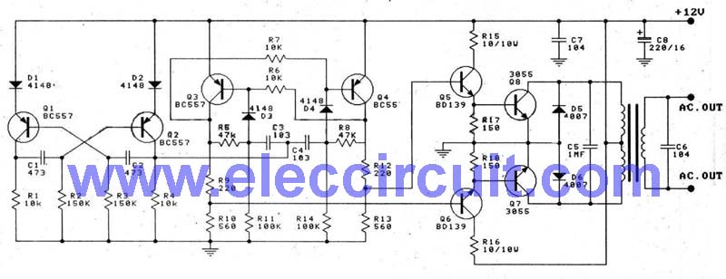
This is a 100-watt transistor inverter circuit diagram that features a straightforward design. The circuit utilizes only transistors, eliminating the need for integrated circuits. It converts a 12V battery input into a 220V output with a 50Hz square wave...
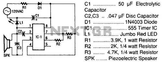
The tester comprises a rectifier circuit and a multivibrator circuit. The alternating current (AC) voltage is half-wave rectified by diode D1 and stored in capacitor C1. Resistor R1 is employed to limit the current through D1 to a safe...
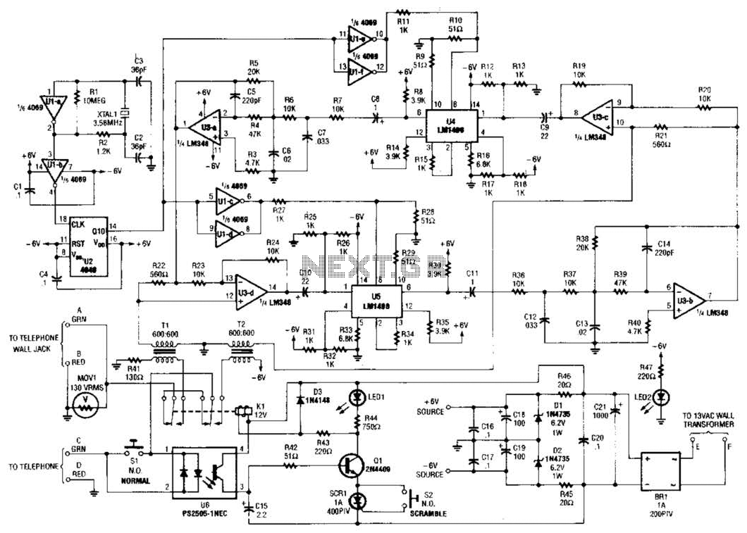
Two hybrids (T1 and T2) are utilized to facilitate a direct connection to a telephone line. This circuit employs a standard speech-inversion algorithm, which inverts the frequency of an audio signal around a central frequency. An LM1496 balanced modulator...
The TDA2822 is a low-power stereo operational amplifier commonly utilized in Walkman devices and headphones. It is capable of delivering an output power of 250 milliwatts. This operational amplifier is particularly suitable for low-volume production applications and serves as...
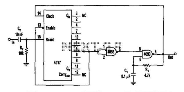
This circuit features a rate multiplier utilizing a 4093 Schmitt trigger configured as an oscillator, which drives a 4017 decade counter. When a pulse is present at the input (to C2), the 4017 is reset, causing output zero to...
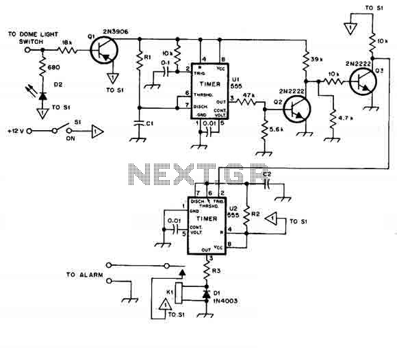
When this car alarm circuit is activated, it remains active for 80 seconds. There is a 15-second delay for the driver to enter and deactivate the alarm. All timings can be easily modified. The circuit utilizes two NE555 timers,...
Warning: include(partials/cookie-banner.php): Failed to open stream: Permission denied in /var/www/html/nextgr/view-circuit.php on line 713
Warning: include(): Failed opening 'partials/cookie-banner.php' for inclusion (include_path='.:/usr/share/php') in /var/www/html/nextgr/view-circuit.php on line 713