
AVR Microcontroller Digital Clock with ATtiny2313


The described AVR Digital Clock project utilizes an ATtiny2313 microcontroller as its core component, showcasing a unique approach by displaying time on an oscilloscope rather than traditional visual outputs like LCDs or seven-segment displays. This design choice highlights the versatility of the ATtiny2313, which is a popular microcontroller known for its compact size and efficient performance in embedded systems.
The circuit design includes various passive components such as resistors and capacitors, which are essential for signal conditioning and timing functions. Specifically, the project employs a range of resistors with values including 120 Ohm (R1), 10K Ohm (R4), 100K Ohm (R2, R5, R6, R7, R10), 120K Ohm (R3), 390K Ohm (R8), and 680K Ohm (R9). These resistors are rated at 1/4 watt with a tolerance of 5%, ensuring reliable performance under typical operating conditions.
Capacitors are also integral to the circuit, with two 47 pF ceramic capacitors (C2, C3) and two 100 nF multilayer capacitors (C1, C4) included to manage the timing and stability of the microcontroller's operation. The crystal oscillator (Y1) operates at 4 MHz, providing the necessary clock frequency for accurate timekeeping.
User interaction is facilitated through a tactile switch (SW1), allowing for manual adjustments or settings to be made easily. Additionally, the circuit includes connectors for easy interfacing, such as a 5-pin strip connector (J1) and a 3V clip connector (J2), which enable the connection of power and other peripherals.
The project is well-documented, with source code and schematic diagrams available for download, making it accessible for enthusiasts and engineers looking to replicate or modify the design. This AVR Digital Clock serves as an excellent example of microcontroller applications in timekeeping, utilizing an oscilloscope for real-time display and offering insights into digital electronics design.Usually we see Digital clock on LCD or 7 segmen. But, this AVR Digital Clock which is designed by Ficara Emilio displayed on Oscilloscope. The project use ATtiny 2313 as the main controller. What an interesting microcontroller project. Source code and schematic available for download..
1 120 Res. 1/4W 5% R1 1 10K Res. 1/4W 5% R4 5 100K Res. 1/4W 5% R2 R5 R6 R7 R10 1 120K Res. 1/4W 5% R3 1 390K Res. 1/4W 5% R8 1 680K Res. 1/4W 5% R9 2 47pF Cond. Ceramico C2 C3 2 100nF Cond. Multistrato C1 C4 1 4MHz Quarzo Y1 1 ATtiny2313 Micro 20 DIP U1 1 Pulsante Tactile switch SW1 1 Connettore Contatti strip 5 J1 1 Connettore Connettore clip 3V J2
🔗 External referenceRelated Circuits
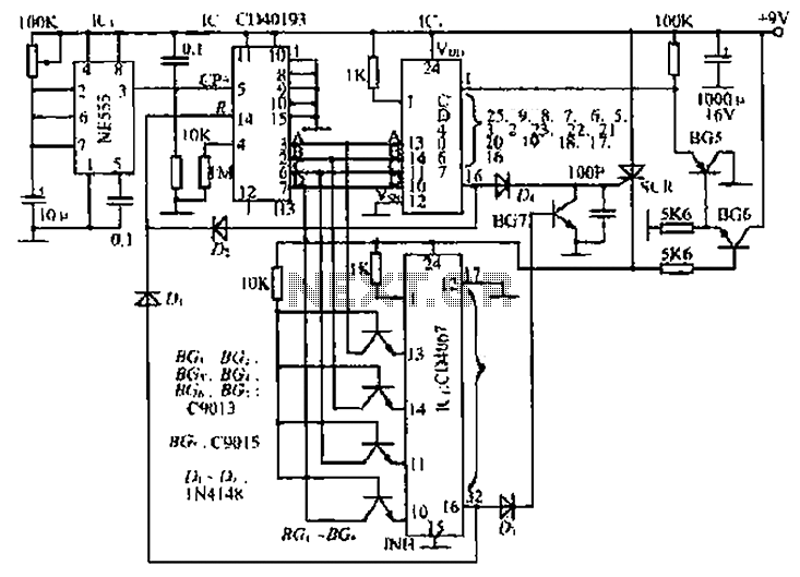
The circuit consists of an oscillator, a counter, and an Iseki circuit divided into three parts. The oscillator is based on the NE555 timer and several external RC components, generating a pulse signal for the counter. The instantaneous power...
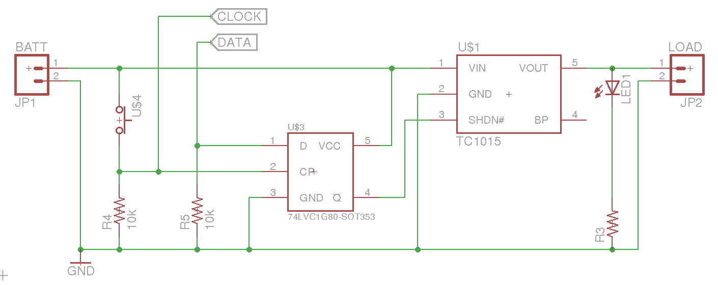
A soft power switch for a microcontroller is designed such that a momentary switch can activate the circuit, including the microcontroller. When the switch is pressed a second time, the microcontroller is capable of shutting itself down after executing...
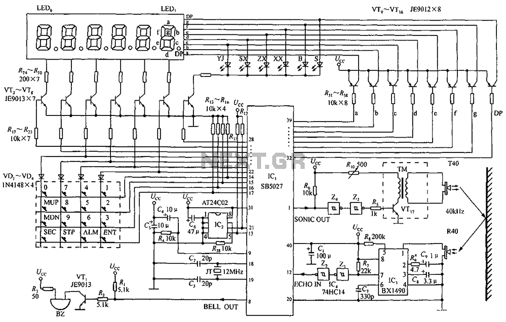
A circuit diagram of an ultrasonic range finder is constructed using a clock with a calendar and the Ultrasonic Ranging IC SB5027. The ultrasonic range finder circuit utilizes the Ultrasonic Ranging IC SB5027, which is designed to measure distances by...
The SP6691 circuit is designed to provide a high output voltage using a lower voltage boost regulator by incorporating a charge pump circuit. This configuration can convert a standard 30V boost regulator into a 60V boost regulator if necessary....
AVR ISP interface (optional but useful if the bootloader is not preferred, if budget constraints prevent the use of JTAG, or if AVR Studio has crashed and disabled on-chip debugging). The following is the updated bill of materials for...
This is the second instructable focused on creating a digital watch as a learning experience. An Atmega644 chip from a Sanguino was available, which would have sufficed, but the intention was to burn an Arduino bootloader and test its...