
Circuit Diagram Based On The 555 Timer IC

The astable circuit utilizing the 555 Timer IC operates in a continuous oscillation mode, generating a square wave output without requiring any external triggering. This configuration is particularly useful in applications such as flashing lights, tone generation, and pulse width modulation.
In this circuit, the 555 Timer is configured in astable mode, which means it alternates between its high and low states. The frequency of oscillation is determined by the resistor and capacitor values connected to the timer. Specifically, two resistors (R1 and R2) and one capacitor (C1) are used to set the timing intervals. The relationship between these components can be described by the formula:
\[ f = \frac{1.44}{(R1 + 2R2) \cdot C1} \]
where \( f \) is the frequency of the output pulse. The duty cycle, or the mark-space ratio, is influenced by the resistor values as well, which can be adjusted to achieve the desired output characteristics.
The output of the 555 Timer is typically taken from pin 3, which can drive loads directly or be interfaced with other circuits. The diode in the circuit may be used for protection against back EMF if inductive loads are connected, ensuring the longevity of the components.
Overall, this astable circuit provides a simple yet effective solution for generating square wave signals, demonstrating the versatility of the 555 Timer IC in practical electronics applications. It is important to select the appropriate component values to achieve the desired frequency and duty cycle for specific use cases.The following circuit shows about Practical Electronics/Plugins/Astable Circuit Diagram. This circuit based on the 555 Timer IC. Features: gives a pulse of about 2Hz with a very low mark-space ratio, used for any number of things, single 555 Astable, plugin is very versatile. Component: IC, Resistor, Diode, Capacitor. [ en. labs. wikime dia. org ] 🔗 External reference
Related Circuits

This is a simple design for a voltage regulator circuit using a pass transistor. The design is built around the LM317T. The output current of the LM317T can be increased by incorporating an additional power transistor to share a...

An electronic lock utilizing a telephone key, which is connected through a resistor plug, is integrated after the oscillator circuit's startup phase. The accuracy of the oscillation frequency determines whether the phone can be used for outgoing calls, while...
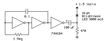
Several 1.5 V LED flasher circuits can be found online, and four of them are presented here. The flasher circuits operate on a single 1.5 V power supply. The design of a 1.5 V LED flasher circuit typically involves a...
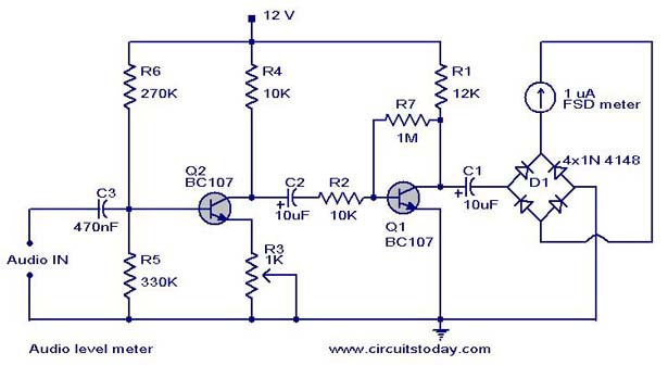
A simple audio level meter or Volume Unit (VU) level meter circuit with diagram and schematic. This sound level meter is designed using transistors with a flat frequency response in the range of 20Hz to 50kHz. The audio level meter...
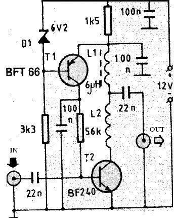
This RF antenna amplifier is designed for high frequency and VHF bands (for radio and TV) and provides a gain of 22 dB. The amplifier features very low noise, measured at under 1.6 dB. The L1 coil has a...
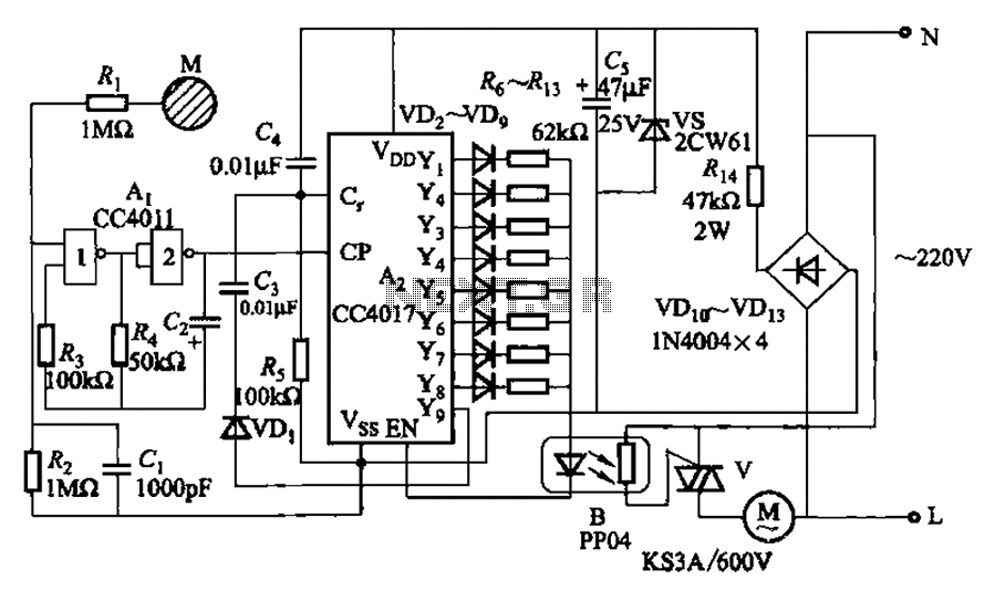
The circuit depicted in Figure 3-7 utilizes a touch sensor chip in conjunction with a conductive sheet. It is designed to achieve eight different speed settings. The CC4011 timing pulse oscillator is comprised of an integrated circuit. The configuration...
Warning: include(partials/cookie-banner.php): Failed to open stream: Permission denied in /var/www/html/nextgr/view-circuit.php on line 713
Warning: include(): Failed opening 'partials/cookie-banner.php' for inclusion (include_path='.:/usr/share/php') in /var/www/html/nextgr/view-circuit.php on line 713