
Circuit Diagram of 0.1 Alpha
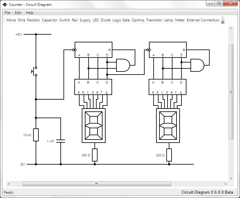
The Circuit Diagram 0.1 Alpha Software is designed as an intuitive platform for creating and editing electronic circuit schematics. It provides users with a variety of tools and features that facilitate the design process, allowing for easy manipulation of components and connections. The software supports a range of electronic symbols and components, including resistors, capacitors, transistors, and integrated circuits, which can be dragged and dropped onto the workspace.
Users can customize their designs by adjusting component values, adding labels, and incorporating various layout options. The software also includes features for simulation, allowing users to test their designs virtually before physical implementation. The open-source nature of the software encourages collaboration and contributions from a community of developers, ensuring continuous improvement and feature enhancements.
Additionally, the software supports exporting designs in multiple formats, making it easier to share and collaborate with others in the field of electronics. Its user-friendly interface is suitable for both beginners and experienced engineers, making it a valuable tool for educational purposes and professional projects alike. The availability of comprehensive documentation and user support further enhances the usability of Circuit Diagram 0.1 Alpha Software.This is Circuit Diagram 0.1 Alpha Software, all free to download and also available open source.. 🔗 External reference
Related Circuits
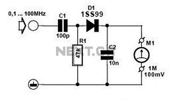
Comprehensive information about RF Probe Circuits is available. Users can learn about and download RF Probe Circuit designs online. RF Probe Circuits are essential tools for testing and analyzing radio frequency signals in various applications, including telecommunications, broadcasting, and electronic...
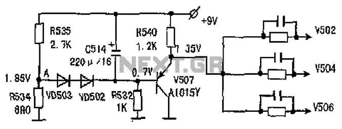
The common-emitter amplifier circuit V502, V504, V506 is designed to generate a static potential bias voltage through an emitter follower configuration, as illustrated in Figure 3. The active filter is formed by components V507, VD502, and VD503. The emitter...
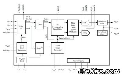
The USB sound card circuit utilizes the PCM2702 integrated circuit (IC) to create a fully functional USB sound card. The design is straightforward, allowing for the easy implementation of audio processing capabilities. The PCM2702 is a versatile USB audio controller...
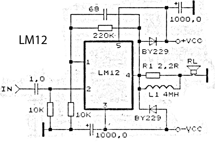
This is an amplifier circuit utilizing the LM12 integrated circuit as the primary amplifier. The amplifier delivers a power output of 150 watts and operates with a load impedance of 4 ohms. It is classified as a high-output power...
The MAX1896, MAX1973, and MAX8863 are integrated circuits that provide output voltages of 5V at 225mA, 1.8V at 220mA, and 3.3V at 60mA, sourced from a USB port. USB devices typically draw power with a voltage range of 4.5V...
This is a design for a flashlight that two 220 V alternating lights can control. The flashlight uses only one IC. IC1a IC1c to be used for the flashing signal generation. The output of IC1c thyristor T1 is controlled,...