
USB Soundcard Circuit with PCM2702
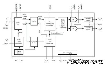
The PCM2702 is a versatile USB audio controller that integrates a USB interface with a digital-to-analog converter (DAC) and an audio codec. It supports a variety of audio formats and is capable of high-quality sound reproduction. The circuit typically includes a few essential components: the PCM2702 IC, passive components such as resistors and capacitors, and connectors for USB and audio output.
To construct the USB sound card circuit, the PCM2702 is connected to the USB power supply and data lines. The IC manages the audio data received from the USB interface and converts it into an analog signal that can be sent to speakers or headphones. Additional components may include decoupling capacitors to ensure stable power supply, resistors for signal conditioning, and a low-pass filter to eliminate high-frequency noise from the output signal.
The output stage of the circuit can be configured to drive headphones directly or to connect to an external amplifier for driving larger speakers. The design can also incorporate a volume control feature using a potentiometer to adjust the audio output level.
Overall, the PCM2702-based USB sound card circuit is an efficient solution for adding audio capabilities to various electronic projects, providing a simple yet effective way to achieve high-quality sound output.Circuit USB Soundcard Circuit with PCM2702 schematics Circuit Electronics, Creating a sound card is not more complex problems. If you useGreat IC PCM2702 from Burr RED / Texas Instruments you can create a cardUSB sound fully functional.
The.. 🔗 External reference
Related Circuits
This circuit illustrates a color sensor circuit diagram. The design is grounded in the principles of optics and digital electronics. The color sensor circuit typically employs a light-sensitive component, such as a photodiode or phototransistor, to detect and differentiate colors...
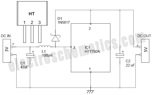
There are several methods to convert an AC voltage from a wall receptacle into the DC voltage required by a microcontroller. Traditionally, this has been accomplished using various types of power supply circuits. To convert AC voltage to DC voltage...
This circuit describes a simple 6-bit random number pseudo-generator used to study binary counters and, in particular, shift registers. Some basic background information about binary counters and shift registers is provided. In reality, there are dozens of different shift...
The purpose of this circuit is for research and education. Assistance is sought in acquiring components for simple RF circuits, as well as tutorials or schematics. The requester is facing challenges in locating quality resources for beginner-level RF circuit...
An operational amplifier designed for medium power applications, utilized as a headphone amplifier capable of driving low loads. The circuit consists of two amplifiers, with a voltage gain set at 40 dB, determined by the resistor pairs R3-R4 and...
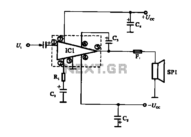
The OCL power amplifier circuit is an integrated circuit. Circuit IC1 is an integrated circuit, and its internal circuit configuration is substantially similar to the OTL power amplifier circuits. The OCL (Output Capacitor-Less) power amplifier circuit is designed to provide...
Warning: include(partials/cookie-banner.php): Failed to open stream: Permission denied in /var/www/html/nextgr/view-circuit.php on line 713
Warning: include(): Failed opening 'partials/cookie-banner.php' for inclusion (include_path='.:/usr/share/php') in /var/www/html/nextgr/view-circuit.php on line 713