
Circuit Diagram Of Simple Infrared Sensor Modules
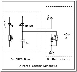
The simple infrared sensor module circuit operates by utilizing an infrared (IR) transmitter and receiver pair. The IR transmitter emits infrared light, which is typically invisible to the human eye. The IR receiver detects the reflected light from objects, allowing the circuit to sense the presence of nearby objects or flames.
In the schematic, the circuit typically includes a power supply, which can be a battery or a DC power source, providing the necessary voltage for the sensor module. The infrared LED serves as the transmitter, while a photodiode or phototransistor acts as the receiver. When the infrared light emitted by the LED hits an object, such as a flame, it reflects back to the receiver, generating a signal.
The output from the infrared sensor can be connected to a microcontroller or an alert system, such as an LED or a buzzer, to indicate the detection of a flame or an object. Additional components may include resistors to limit current and capacitors for filtering noise in the signal.
This circuit design is widely used in various applications, including fire detection systems, automatic lighting systems, and proximity sensors, due to its simplicity and effectiveness in detecting infrared signals. Proper calibration and positioning of the sensor are crucial to maximize its sensitivity and accuracy in detecting flames or nearby objects.The following circuit shows about Simple Infrared Sensor Modules Circuit Diagram. Feature: simple infrared sensor module, flame detection, .. 🔗 External reference
Related Circuits

The car battery charging current is automatically limited to 4.2A. If there is a 600mV voltage on R1 (indicating 4A flowing through it), the T1 transistor begins to conduct. This prevents excessive charging current as the base current of...

The differentiator circuit is an application circuit derived from mathematical principles influenced by capacitor behavior. The circuit, as illustrated in the accompanying image, is a simple differentiator configuration. To derive the differentiator formula, the following sequence is used: Ic...

The 555 Timer facilitates a low-loss single-shot circuit and interfaces with the CMOS4011B NAND gate circuit. The standby power consumption is less than 50 µA. When the one-shot circuit is activated, the current consumption is 4.5 mA, and the...
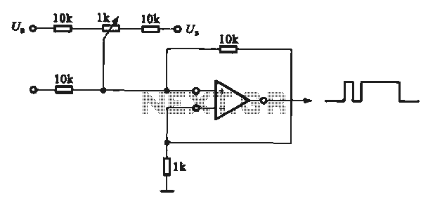
This circuit demonstrates the application of various types of pulse signal generating circuits using operational amplifiers. The circuit utilizes operational amplifiers (op-amps) to create different forms of pulse signals, which are essential in many electronic applications, including waveform generation, timing...

The rewiring of an entire house is underway following a significant malfunction of two antique knob and tube circuits. A challenge has arisen with the outdoor lighting setup, specifically concerning a detached garage that features a porch light above...

This design circuit is used to activate circuitry and an analog meter for sensitive DC current measurements. A subsequent inquiry raised the possibility of measuring AC microamperes, which inspired the idea for this circuit. The circuit is designed to facilitate...