
Circuit explanation of DC/AC inverter

The square wave oscillator circuit is designed to generate a stable square wave output using CMOS logic inverters. The frequency of the oscillator can be adjusted by varying the resistance through a variable resistor in conjunction with a capacitor, allowing for operation at either 50 Hz or 60 Hz. The selection of these values is critical, as they determine the oscillation frequency, which is essential for the proper functioning of the DC/AC inverter.
The output from the oscillator is a TTL signal, which is typically between 0V and 5V. This signal is insufficient to drive the power MOSFETs directly; therefore, a level shifting mechanism is implemented to convert this signal into a higher amplitude of 0V to 12V. This conversion is necessary to ensure that the MOSFETs can be switched adequately to handle the power levels required for the inverter operation.
The inverter circuit employs a push-pull configuration using complementary MOSFET pairs (TR3, TR4 and TR5, TR6). This arrangement allows for efficient switching and control of the current flowing through the transformer. The antiphase control strategy ensures that when one pair of transistors is conducting, the other pair is turned off, preventing short circuits and allowing for the alternating current to be generated in the transformer secondary.
In practical applications, attention must be given to the choice of components, particularly the MOSFETs, which must be rated for the expected current and voltage levels. The inclusion of a fuse is a critical safety feature, providing protection against overcurrent conditions that could potentially damage the circuit components or lead to hazardous situations.
Overall, this square wave oscillator and inverter circuit represents a fundamental design approach for converting DC to AC power, suitable for various electronic applications requiring an inverter solution.This is the square wave oscillator which used a CMOS-type logic inverters. I use the word "logic inverter" to avoid confusion with the DC/AC inverter. The output of the oscillator is connected with the drive circuit through the logic inverters. The antiphase signal of the alternating current is created using the logic inverter, too. Connect the in put of the logic inverters not to be using with the grounding to avoid bad influence. I chose resistance and capacitor for the oscillator in the following value. I calculated that it was possible to set to 50 Hz or 60 Hz with the variable resistor. Because there is an error of the part in the actual circuit, it is a reference value. Because the output of the oscillator is the TTL of 0V to 5V, it is converted into the amplitude of vibration of 0V to 12V to drive an FET with this circuit. It is not a special circuit. This is the switching circuit which is the main circuit of the DC/AC inverter this time. I used C-MOS FET circuit by power MOS FET. Two sets of C-MOS FET circuits are used and are controlled by the antiphase. In case of the input of TR3 and TR4 are L level and the input of TR5 and TR6 are H level, TR3 and TR6 become ON condition and TR4 and TR5 become OFF condition.
Therefore, the electric current flows through the direction of A to B to the secondary coil(12V side) of the transformer. When the input level is opposite, TR3 and TR6 become OFF condition and TR4 and TR5 become ON condition.
Therefore, the electric current which flows through the transformer becomes contrary to the case of the above. Either above-mentioned condition is continued when the oscillator stops. Therefore, the big electric current flows on the secondary side of the transformer. The fuse must be put to protect. 🔗 External reference
Related Circuits
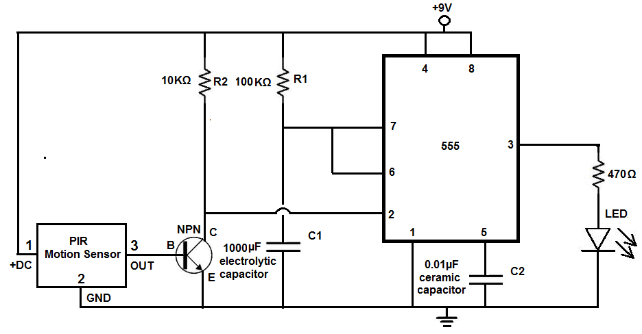
Many individuals install motion detectors in their backyards or homes to automatically turn on lights when movement is detected. Motion sensor lights have gained popularity and are increasingly utilized in various settings. Businesses frequently employ them in bathrooms, where...
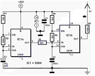
The output frequency alternates between approximately 2100 Hz and 2200 Hz. This unique test signal is easily distinguishable from other potential signals. Resistor R6 is connected to a wire, approximately ten centimeters long, which serves as the antenna. The...
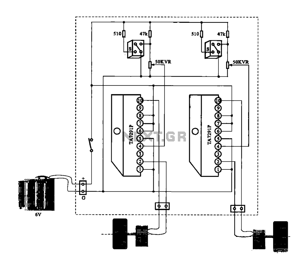
A dual motor drive circuit for automatic tracking consists of two motors that are part of a car structure, which operates based on the principles of a double motor drive system. The dual motor drive circuit is designed to facilitate...
This circuit switches a printer's USB connection from a PC to a laptop. The objective was to create a solution that enables a laptop to use the printer intermittently while maintaining the printer's primary connection to the PC. Instead...
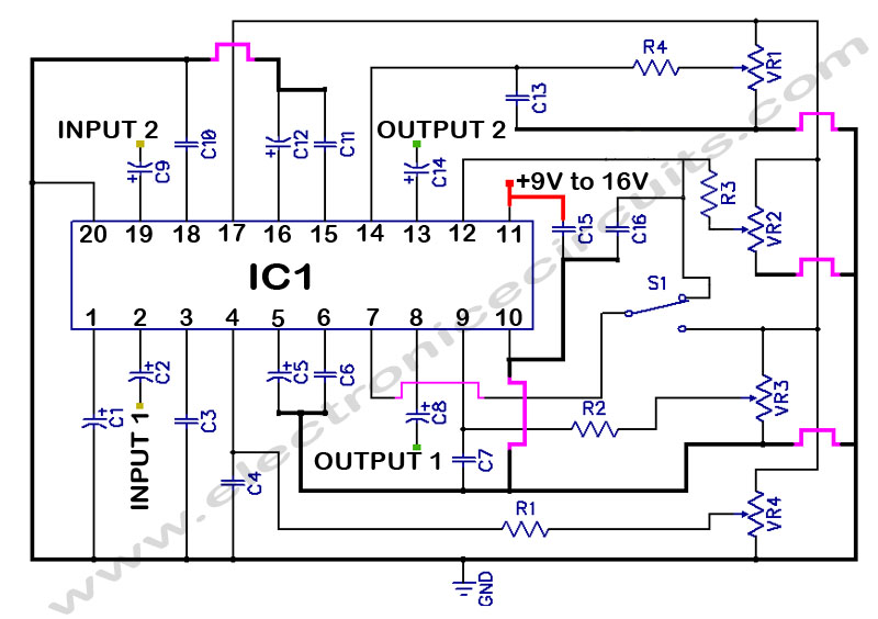
LM1036 Stereo Tone (Bass, Treble, Volume, Loudness, Balance) Controller Circuit. The LM1036 is a DC controlled tone (bass/treble), volume, and loudness controller designed for audio applications. The LM1036 circuit serves as an integrated solution for controlling various aspects of audio...
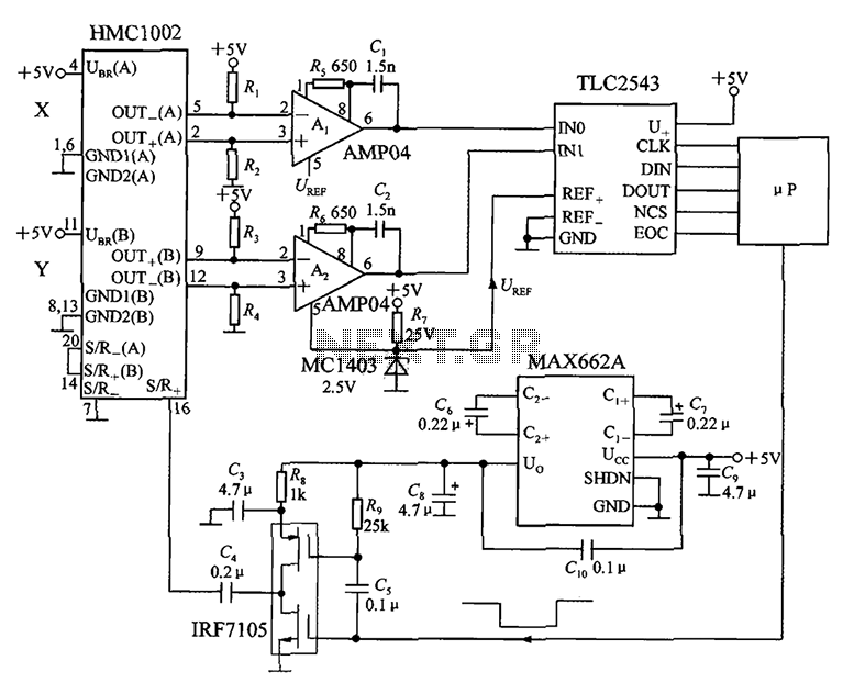
An application circuit for a biaxial magnetic field sensor is presented. This circuit utilizes the HMC1002 biaxial magnetic sensor along with two AMP04 amplifiers (A1, A2) to simultaneously measure magnetic fields in both the X-axis and Y-axis directions. The...