
wire tracer circuit

The circuit described operates within a frequency range that allows for effective signal transmission and reception, which is critical for applications such as wire tracing and fault detection. The use of a 556 timer, which contains two timing circuits, enhances the functionality of the transmitter by enabling frequency modulation. The first timer (IC1b) generates a square wave signal, while the second timer (IC1a) modulates this signal, providing a variable output frequency that can be adjusted for optimal performance based on the specific requirements of the testing environment.
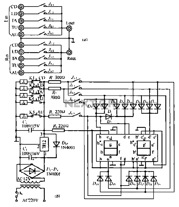
The antenna, a simple wire connected to resistor R6, plays a crucial role in radiating the generated signal. Its length is carefully chosen to optimize the transmission characteristics at the frequencies being used. The ground connection ensures that the circuit operates effectively by providing a stable reference point, which is essential for accurate signal transmission and reception.
This device is particularly beneficial for technicians and electricians who need to trace wiring paths or locate breaks without the need for invasive methods. The straightforward design allows for easy assembly and use, making it accessible for both professionals and hobbyists. By employing this circuit, users can efficiently identify and troubleshoot wiring issues, improving overall maintenance and repair processes in electrical systems.The output frequency alternates between about 2100 Hz and 2200 Hz. This is a very distinctive test signal that is easily distinguished from any other signals that may be present. Resistor R6 is connected to a piece of wire, about ten centimeters long, that functions as the antenna. The ground connection (junction C2-C3) is connected to ground. When the antenna is connected directly to a cable, it is possible to determine at the other end of the cable, with the aid of the receiver, which conductor is which (don`t do this with live conductors!).
The schematic for the matching receiver may be found elsewhere in this website. The circuit depicted here forms one half of a device that will prove extremely handy when tracing the path of electrical wiring in a building or to locate a break in a wire. The system is based on similar equipment that is used by technicians in telephone exchanges. The operation is straightforward. You require a generator that delivers an easily recognizable signal which, using a short antenna, is inductively coupled to a simple, but high gain, receiver.
To create a useful transmitter it would suffice to build a simple generator based on a 555. But as the adjacent diagram shows, a 556 was selected instead. The second timer (IC1a) is used to modulate the tone produced by IC1b. 🔗 External reference
Related Circuits

This simple water level sensor circuit monitors the presence of water in a specific location or container. The circuit activates an acoustic alarm when it detects water. The water level sensor circuit typically consists of several key components, including a...
Can simulate the character Mu symbol. A bone dish SET code is needed that effectively manages the decimal point. An inverted J is required to open its mouth. Left foot circuit diagram. The project involves designing a circuit that simulates...
The circuit operates without a base current for the transistor. It turns off when the metal sheet is touched, causing the capacitor to start charging. The capacitor charges to 2V over a specified time. The circuit generates a conduction...
This is a game timer circuit diagram. When the game timer is reset, two actions must occur: the 4017 counter must return to zero, and the 4060... The game timer circuit utilizes the 4017 decade counter and the 4060 binary...
Operating radio transmitters without a license is illegal in most countries, so caution is advised with transmitter circuits. This FM low-power circuit is designed to operate within the 87-108 MHz band II, providing a range of approximately 20 to...

This is a simple power resumption alarm circuit that can be installed within the switch box. It emits beeping sounds when power is restored following a power outage. The power resumption alarm circuit serves as a practical solution for alerting...
Warning: include(partials/cookie-banner.php): Failed to open stream: Permission denied in /var/www/html/nextgr/view-circuit.php on line 713
Warning: include(): Failed opening 'partials/cookie-banner.php' for inclusion (include_path='.:/usr/share/php') in /var/www/html/nextgr/view-circuit.php on line 713