
circuit How to find currents of all nodes using superposition theorem
The superposition theorem is a fundamental principle in circuit analysis that allows for the simplification of complex circuits by considering the contribution of each independent source separately. In this context, the circuit under analysis contains three nodes, and the goal is to find the currents at these nodes by applying the superposition theorem effectively.
To begin, each independent source in the circuit should be analyzed one at a time. When examining the effect of a voltage source, all other voltage sources must be replaced with short circuits, while current sources are replaced with open circuits. For example, when analyzing the source associated with V1, the circuit should be modified accordingly to isolate its effects. The calculated current through V1, referred to as i_1, reflects the influence of this source alone.
After determining the current contributions from each source, the next step involves summing these individual currents at each node. This approach allows for the accurate calculation of total current flowing through the circuit when all sources are considered simultaneously. It is crucial to maintain awareness of current directions during this process. Current direction can be denoted using arrows, with the understanding that if the actual current flows contrary to the drawn arrow, it will yield a negative value in the final analysis.
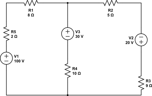
To enhance understanding, it is recommended to include a schematic diagram of the circuit, clearly labeling each node and current direction. This visual representation will facilitate comprehension of the circuit behavior and the application of the superposition theorem, making it easier to track currents and validate calculations. By following these steps, a comprehensive analysis of the circuit can be achieved, ensuring all currents are accounted for and accurately represented.Using the superposition theorem, I need to find the current of all the 3 nodes of the circuit. Using superposition I`ve found that the current from the source: Do you mean i_1 is the current through V1 when the other voltage sources are shorted out, in line with the first step of solving the problem with super position Davorak Mar 6 `13 at 21 :51 @Davorak: Yes! The 2nd one is exactly what I mean. I`ve shorted it out finally, I hadn`t calculated all the other currents at the nodes when I was applying superposition. I did now, and all the currents are correct. Chris Mar 6 `13 at 23:28 After you have solved the circuit for each source individually you can add together the currents of each branch to get the total current of the final circuit with all sources.
I it is not possible, with out solving the circuit in some fashion to know the directions of current you are taking about in your questions. It would be a good idea to include a diagram like on fo the below or add an up/down, left/right annotation to your current where appropriate.
You can draw your current arrows in any direction you want, if the current is actually flowing in the opposite direction of your arrow then then it will just end up being a negative current in your solution. 🔗 External reference
Related Circuits
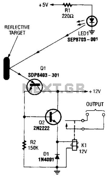
A reflector isolator detects the presence of an object by bouncing light off of it. This technique is useful in circuits that detect when an object is close enough to the sensor. A reflector isolator is a type of optical...
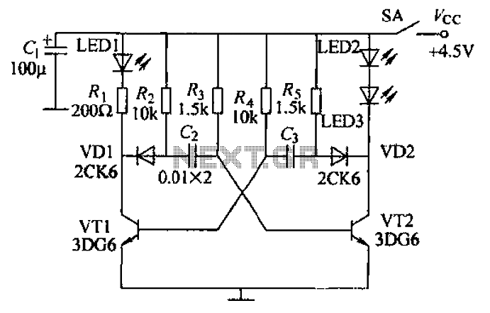
Transistors VT1, VT2, and associated RC components are configured to form a multivibrator. The multivibrator operates with resistors Ra and R4 serving as base bias resistors for VT2 and VT1, respectively. When the switch SA is closed after applying...
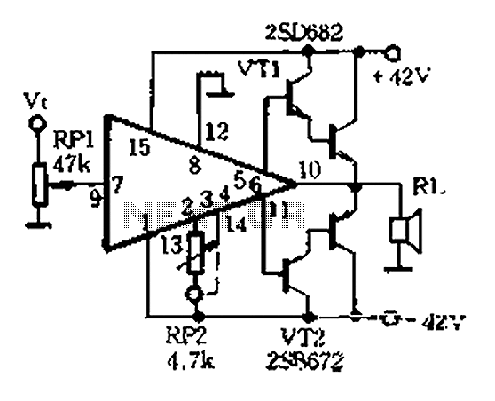
The AP500A amplifier offers numerous advantages, providing unmatched superiority in stereo applications. It can utilize various amplifier configurations, including OTI, CI, rK, BTL, class AB, and super CP. The typical DC amplifier module for the AP500A is illustrated in...
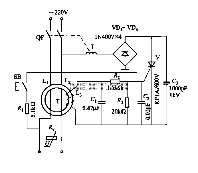
DBS-20 type leakage protection circuit The DBS-20 type leakage protection circuit is designed to detect and prevent electrical leakage, thereby enhancing safety in electrical installations. This circuit operates by monitoring the current flowing through the live and neutral conductors. When...
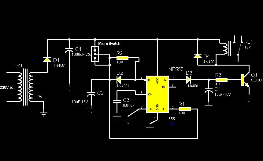
The circuit diagram illustrates a rotation sensor that activates a device, such as a motor or buzzer, when the circuit assembly is rotated. The design is based on the fundamental operation of a 555 timer. The rotation sensor circuit utilizes...
This project uses a 3909 IC and a few other parts; power is 1.5 volts DC. The project employs the 3909 integrated circuit (IC), which is a versatile component commonly used in various electronic applications, particularly in timer and oscillator...
Warning: include(partials/cookie-banner.php): Failed to open stream: Permission denied in /var/www/html/nextgr/view-circuit.php on line 713
Warning: include(): Failed opening 'partials/cookie-banner.php' for inclusion (include_path='.:/usr/share/php') in /var/www/html/nextgr/view-circuit.php on line 713