
50Mhz Rf Bridge Circuit
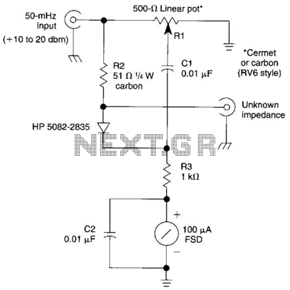
The described bridge circuit is designed specifically for measuring the impedance of 50-MHz amateur radio antennas, which is crucial for ensuring optimal performance and matching in radio frequency (RF) applications. The circuit employs a potentiometer, Rl, with a resistance of 500 ohms, allowing for fine adjustments in the measurement process. This miniature potentiometer facilitates the balancing of the bridge, enabling accurate readings of the unknown impedance.
In the configuration, the unknown impedance is compared against a known resistor, R2, which has a value of 51 ohms. This comparison is essential for determining the characteristics of the antenna under test. The use of a known resistor provides a reference point, allowing the user to calculate the unknown impedance based on the bridge's balance condition.
An external signal source is necessary to provide the excitation signal for the bridge circuit. This signal source generates a test frequency of 50 MHz, which is the operational frequency of the amateur radio antennas being measured. The signal is applied across the bridge, and the resulting voltage readings are analyzed to determine the impedance characteristics.
The overall design of the bridge circuit must ensure minimal signal loss and distortion at the operating frequency. Proper layout and component selection are critical to maintaining the integrity of the measurements. Additionally, care should be taken to minimize parasitic capacitances and inductances, which can adversely affect the accuracy of the readings.
In summary, this bridge circuit serves as a vital tool in the characterization of 50-MHz amateur radio antennas, leveraging a combination of a linear potentiometer and a known resistor to facilitate precise impedance measurements, supported by an external signal source for effective operation. The bridge shown was used for measurements on 50-MHz amateur radio antennas. Rl is a miniature 500 linear potentiometer. The unknown impedance is compared to R2, a 51- resistor. An external signal source is required. 🔗 External reference
Related Circuits

The AC power supply voltage is normal, and a relay is connected to the load (Rfz) circuit. In the event of a load short-circuit failure, the voltage across relay KA drops rapidly, causing KA to release and disconnect the...

This simple square-wave generator produces a variable frequency output ranging from 2800 Hz to 80 kHz, as indicated by the specified values. The frequency can be adjusted using potentiometer R1. The square-wave generator circuit typically employs a combination of resistors,...
A simple USB FM transmitter that can be used to play audio files from an MP3 player or computer on a standard VHF FM radio by connecting it to a USB port. The circuit does not require any coils...

The SOS Alarm centralized control circuit is designed for use in calling a hospital bed and can also serve as an anti-theft alarm in multi-storey buildings, dormitories, warehouses, and similar locations. The circuit, as depicted in Figure 13-64, features...
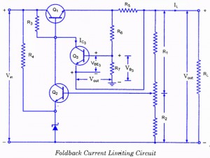
If the load resistance (RL) is reduced or the load terminals are accidentally shorted, a very large load current will flow, potentially damaging the pass transistor (Q1), diode, or other components. Fuse protection may not be sufficient, as the...
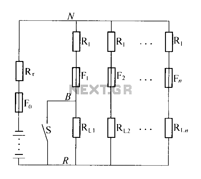
The circuit diagram illustrates a high-impedance distribution system characterized by low resistivity distribution. A notable feature is the series resistance of the shunt load current limiting resistor R1, typically valued at five to ten times the internal resistance of...