
Using tap potentiometer loudness circuit
The circuit described in Figure 1.88 is a sophisticated implementation of loudness control, commonly used in audio amplification systems to enhance the listening experience at lower volume levels. The design leverages the properties of resistors and capacitors to create a frequency-dependent response that compensates for the human ear's reduced sensitivity to lower sound levels, particularly in the bass and treble ranges.
The RC compensation network is crucial for adjusting the frequency response based on the potentiometer's position. When the potentiometer is set to lower volume levels, the input signal experiences significant attenuation due to the resistive divider formed by the potentiometer. The capacitive reactance, characterized by the capacitor's value (cl), plays a pivotal role in shaping the frequency response. At lower volumes, the high-frequency components are attenuated more than low frequencies, resulting in an enhanced bass response, which is essential for maintaining a balanced sound profile.
The configuration of the taps on the potentiometer allows for flexibility in sound tuning. The double-tapped circuit (Figure b) offers a more nuanced approach, providing tailored compensation across a broader range of volumes. This design ensures that listeners can enjoy a consistent audio experience, regardless of the volume setting. The single-tap switch (Figure c) adds functionality by allowing the user to bypass the compensation network for high signal levels, ensuring that the audio remains uncolored and true to the source material during loud playback.
In contrast, the simple single-tap design (Figure d) focuses solely on bass compensation, making it particularly useful in applications where treble enhancement is not desired. This design is beneficial in universal amplifiers that cater to a wide range of audio sources, allowing for straightforward integration without complex adjustments.
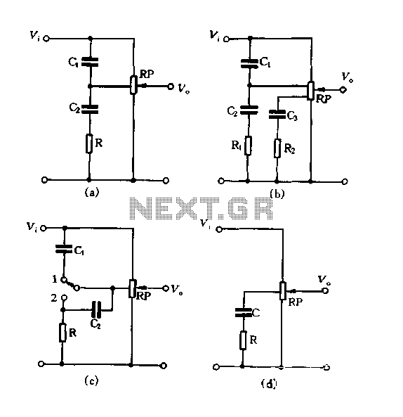
Overall, the described potentiometer control circuit exemplifies a well-engineered solution for dynamic audio environments, providing listeners with the ability to fine-tune their audio experience while maintaining fidelity across various listening conditions.Figure 1.88 using the loudness of several tapped the potentiometer control circuit. In FIG. (A), and between the tap and the input of the potentiometer and the land respectivel y, then A RC compensation network, when the slide point to the nearby rotary potentiometer tap (ie small volume), high, bass can be obtained make up. It works like this : In the small volume, the input signal through the RP partial pressure attenuation silver big, but cl capacitive reactance with frequency and reduce the rate of rise of the audio signal in a high- points can be by cl and tap the potential, sent directly to the output terminal, is greatly attenuated Tibetan small, that treble relatively be enhanced; connected to the potentiometer tap and the ground between the islands larger capacity, capable of the high audio attenuate the same time, that is, from relatively enhanced bass effect; the maximum attenuation (ie low treble sound relatively lift) by R determines the size.
Even at high volume, point to the upper end of the slide potentiometer, away from the tap position, it can not afford to make progress RC element effects, flat frequency response of the output signal. Such sound effects and potential of the control compensation circuit pumping head location of: tap positions higher compensation more early action, but the lift is reduced o Figure (b), (c) - (d) are several other commonly used form of compensation circuit.
Figure (b) is double-tapped, the circuit is more complex, but it was big, medium and small volume can give appropriate compensation, the best results. Figure (c) is a single tap changer type switch is set to 1 when the circuit (a), as applicable to normal signal input; when placed in the 2 position, the compensation network out of action for a strong signal input.
Figure (d) is a simple one-tap type, only compensation for bass, treble without compensation, and more for universal amplifiers.
Related Circuits
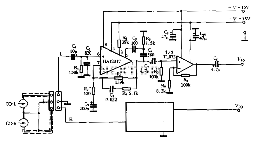
Figure 3-16 illustrates a low-noise preamplifier equalizing circuit using the HA12017. This circuit includes playback components R3, R4, and C4, which conform to a standard balanced network. The gain of the circuit is -7dB at 1kHz, while the output...
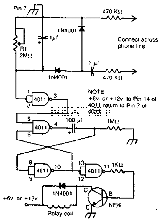
By cross-connecting the telephone ringing circuit, when the phone rings, the circuit activates the relay. It utilizes a delay in contact to drive various devices such as bells, sirens, buzzers, or lights. The telephone ringing circuit is designed to detect...
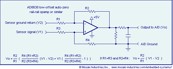
Ground loop offset errors and ground noise are eliminated by a differential amplifier or instrumentation amplifier before the analog-to-digital (A/D) conversion. The differential input amplifier addresses ground loop errors, allowing for precise measurement of non-isolated sensors. A simple operational...
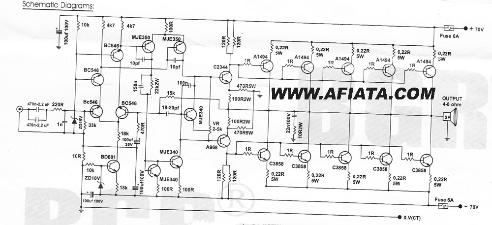
How many speakers can be attached to this amplifier, and what are the impedance and wattage values of these speakers? Please respond to my email. Sir, you made this amplifier, and it works properly for a lifetime. Which transformer...
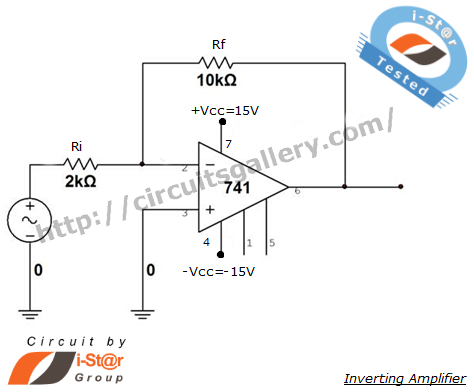
An inverting amplifier is one of the most widely used operational amplifier circuits. The output adjusts in a manner that counteracts changes caused by the input, thereby preventing saturation and ensuring stability. By connecting a resistor from the output...
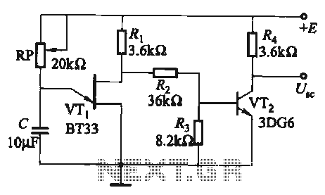
The circuit comprises a single-junction transistor VTi, a resistance Ri, a potentiometer RP, and a capacitor C, forming a relaxation oscillator and an amplifier transistor VTz. The adjustment potentiometer RP allows for changing the relaxation oscillation frequency, providing a...