
Twilight switch circuit
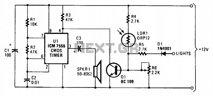
The circuit employs a cadmium-sulfide light-dependent resistor (LDR) to monitor ambient light levels and control an audible alert system through a horn. The operation begins with the LDR, which varies its resistance based on the surrounding light conditions. In bright light, the resistance of LDR1 is low, approximately 100 ohms, allowing sufficient base current to flow into transistor Q1, which is configured as a switch. The voltage divider formed by R4, LDR1, and the adjustable potentiometer R6 determines the base voltage of Q1, allowing for calibration based on the desired light threshold.
When ambient light diminishes, the resistance of LDR1 increases significantly, leading to a decrease in base current to Q1. This reduction in current causes Q1 to turn off, allowing the oscillator circuit to become active, thereby triggering the horn. The oscillator's output is connected to pin 4 of operational amplifier U1, which is configured to mute the sound when Q1 is conducting.
The inclusion of diode D1 serves a critical protective function. It is connected to the vehicle's parking light switch, ensuring that when the lights are off, the circuit remains inactive, as D1 blocks any backflow of current from the parking lamp circuit. This design prevents unwanted activation of the horn when the vehicle's lights are not in use. Conversely, when the parking lights are turned on, D1 allows current to flow to the base of Q1, biasing it into conduction and effectively muting the oscillator, even if the ambient light conditions would otherwise suggest it should be active.
Overall, this circuit serves as a practical solution for ensuring that vehicle lights are turned on at dusk, utilizing simple yet effective electronic components to monitor light levels and provide an audible reminder. The careful arrangement of resistors, the LDR, and the transistor ensures reliable operation and user convenience.As dusk begins to -fall, the sensor (a cadmium-sulfide light-dependent resistor or LDR) operates a small horn to provide an audible reminder that it's time to turn on your lights. To turn the circuit off—simply turn your headlights on and the noise stops. The base of Ql is fed through a voltage divider formed by R4, LDR1—a light-dependent resistor with an internal resistor of about 100 ohms under bright-light conditions and about 10 megohms in total darkness—potentiometer R6.
Ql's base voltage depends on the light level received by LDR1 and the setting of R6. If LDR1 detects a high light level, its resistance decreases, thereby providing a greater base current for Ql, causing it to conduct. When Ql conducts, pin 4 of Ul is pulled to near ground potential, muting the oscillator. If, on the other hand, LDR1 detects a low light level, its resistance increases (reducing base currentto Ql), cutting off the transistor and enabling the oscillator. In actual practice, you set R6 so that at a suitable light level (dusk), the oscillator will sound. The anode of diode Dl connects to the light switch, where it connects to the vehicle's parking lights.
With the lights switched off, that point is connected to the negative chassis by way of the parking lamp. That has no effect on the circuit, as Dl blocks any current flow to ground from Ql's base via R6 and the sidelight lamps.
When the lights are switched on, the anode of Dl is connected to the positive supply via the parking lamp switch, thereby applying a voltage to the base of Ql, biasing it into conduction. With Ql conducting, pin 4 of Ul is pulled virtually to ground, disabling the oscillator even though LDRl's resistance is not enough to do so.
🔗 External reference
Related Circuits
The project involves a DC geared motor intended for use in a suitcase carrier. Two motors were purchased from Pololu at a cost of approximately $100. The selection process included discussions among team members, followed by consultation with Dr....
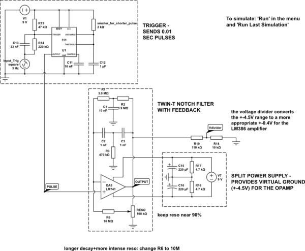
The circuit is constructed on a breadboard and produces the expected sound characteristics, specifically a damped sine wave reminiscent of large 808/909-style kicks. However, it exhibits a significant amount of noise. An attempt was made to mitigate this by...

The time constant of RAXC determines the period of the monostable multivibrator. A negative pulse at pin 2 of the 555 starts the cycle. The monostable multivibrator is a circuit configuration that produces a single output pulse in response...

This is a simple toggle switch that can be operated through sound signals such as a whistle or clap. The output of the toggle remains either low or high until... This circuit utilizes a sound sensor to detect specific audio...
This project involves a light-activated alarm or morning alarm circuit that produces a pleasant melody upon detecting light. To use this circuit as a morning alarm, it should be placed in a location that receives morning sunlight. A 500K...

The power supply terminal should utilize a 1 µF chip capacitor filter, positioned as close as possible to the chip's supply pin. The signal is generated by the input pins 2 and 3. The source resistance of the signal...