
Temperature-controlling circuit
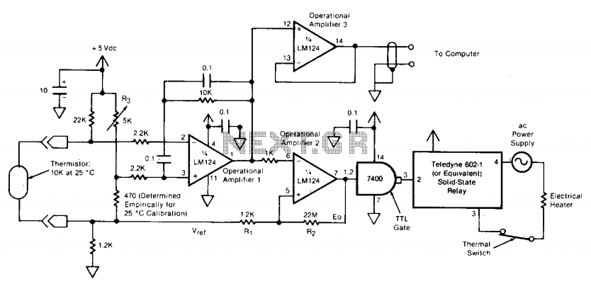
The described circuit is a temperature control system designed to maintain a stable environment in a room by regulating an electrical heater. The core component of the system is a thermistor, which acts as a temperature sensor. This thermistor provides a differential voltage input to an operational amplifier, ensuring minimal noise interference in the signal. The operational amplifier converts the analog signal from the thermistor into a format suitable for further processing.
A 5 kilohm potentiometer is integrated into the design to allow for user-adjustable temperature settings. By configuring the potentiometer as part of a voltage divider, the desired set point can be fine-tuned. Specifically, setting the potentiometer to 2.17 kilohms will achieve the target temperature of 25°C.
The circuit employs a second operational amplifier configured as an inverting differential-input comparator. This comparator compares the voltage from the thermistor with the reference voltage set by the potentiometer. When the temperature deviates from the set point, the comparator's output changes state, signaling the need to activate or deactivate the heater.
Control of the heater is accomplished through a zero-crossing solid-state relay, which is triggered by the output of the second operational amplifier. This relay allows for efficient switching of the AC supply to the heater, minimizing electrical noise and potential damage to the components.
To ensure the reliability and safety of the system, a transistor/transistor-logic (TTL) gate is included to condition the output from the operational amplifier for the relay control. Additionally, a thermal switch is placed in series with the heater and the AC supply. This switch serves as a safety mechanism, disconnecting the heater in the event of a thermal runaway situation, thereby preventing overheating.
Finally, a third operational amplifier is utilized to monitor the thermistor output continuously. This amplifier provides a real-time signal to a computer system for data logging purposes, enabling users to track the temperature variations over time and make informed decisions regarding heating requirements. Overall, this circuit exemplifies an effective thermal management solution for maintaining desired ambient conditions in a controlled space.The circuit switches the current to an electrical heater on and off to maintain the temperature of a room at 25 ±0.5°C. The temperature sensor is a thermistor which provides a differential input (for reduced noise) to an operational amplifier.
A 5 kilohm potentiometer is used to adjust the set point through a voltage divider; a value of 2.17 kilohms yields the 25° C setting. A second operational amplifier is connected as an inverting differential-input comparator. The output of operational amplifier 2 controls the electrical heater through a zero-crossing solid-state relay.
A transistor/transistor-logic (TTL) gate adjusts the output to the proper level for the relay. A thermal switch is placed in series with the heater and the ac supply for safety in case of thermal runaway. A third operational amplifier monitors the output of the thermistor, providing a signal to a computer for data logging.
🔗 External reference
Related Circuits
Also known as a megger insulation resistance meter, this device measures resistance at the megohm level. It is primarily used to assess the insulation resistance of motors, electrical circuits, and equipment. Additionally, it helps determine whether there is circuit...
Nissan Sentra 1.6 Liter Manual Transmission Starter Circuit Wiring Diagram. The Nissan Sentra 1.6 Liter manual transmission starter circuit wiring diagram provides a visual representation of the electrical connections involved in the starting system of the vehicle. This diagram is...
An AC contactor DC transformer circuit operates as a voltage regulator for AC applications. DC contactors come in various types. AC contactors are electromechanical devices used to control the flow of electrical power in AC circuits. They function by opening...
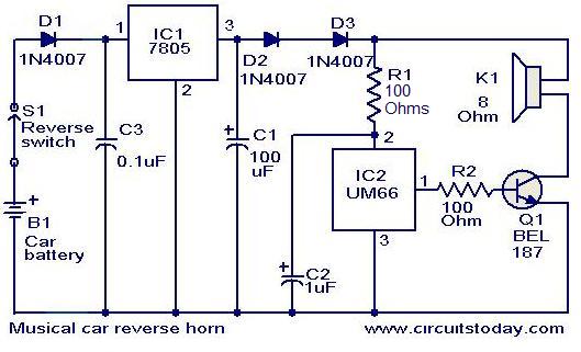
This circuit is designed to produce a musical horn whenever a car is in reverse gear. It utilizes two integrated circuits (ICs) for its operation: a voltage regulator (7805, referred to as IC1) and a musical tone generator (UM66,...

This simple PC scope probe functions as a FET follower, featuring high input impedance and low output impedance to match a microphone or line input socket on a PC or laptop. This design allows for practical examination of waveforms...

This is a simple FM transmitter circuit schematic diagram that utilizes a single transistor, S9014. The FM transmitter circuit operates by modulating an audio signal onto a carrier frequency, which is typically in the FM band. The S9014 transistor serves...
Warning: include(partials/cookie-banner.php): Failed to open stream: Permission denied in /var/www/html/nextgr/view-circuit.php on line 713
Warning: include(): Failed opening 'partials/cookie-banner.php' for inclusion (include_path='.:/usr/share/php') in /var/www/html/nextgr/view-circuit.php on line 713