
Circuits Diagram: Simple 40W inverter
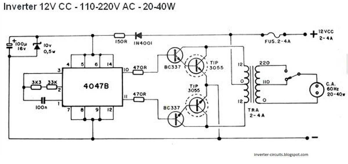
This inverter circuit is designed for efficiency and simplicity, making it accessible for hobbyists and engineers alike. The CD4047 IC serves as the oscillator, generating the necessary frequency for the inverter operation. The choice of a 60Hz output frequency aligns with standard AC power supplies in many regions, making it suitable for various applications.
The complementary symmetry amplifier configuration, utilizing BC337 and TIP3055 transistors, is critical for boosting the low-level signals produced by the CD4047 to a level sufficient to drive the transformer. The BC337 transistor is a low-power NPN transistor, while the TIP3055 is a high-power NPN transistor, providing the necessary current handling capabilities for the output stage.
The transformer plays a vital role in stepping up the voltage from the 12V input to the desired output voltage. The recommendation for a 220-110-0 primary and 12-0-12 secondary transformer allows for flexibility in output voltage selection. The two-way switch enables users to easily switch between 110V and 220V outputs, catering to different appliance requirements.
In cases where the specified transformer is not available, using a 220V to 12-0-12 transformer is a viable alternative. However, this will limit the output to 12V and 220V, omitting the 110V option. Salvaging components from discarded electronics is a practical approach to acquiring necessary parts, particularly transformers.
When assembling the circuit, it is advised to focus on the oscillator section first, ensuring that the output waveforms at pins 10 and 11 of the CD4047 are verified before proceeding. This step is crucial for confirming that the circuit is functioning correctly before integrating the amplification and transformer stages. Proper attention to wiring and component placement on the PCB will enhance the reliability and performance of the inverter circuit.This is the schematic of a simple 40W, 12 to 220 V inverter. You don`t believe, this is simple and cheap and working for me for last 4 years. The heart of the circuit is a CD 4047 IC which is wired as an astable multi vibrator here. Resistance and Capacitance at pin 1&2 determines the out put frequency. Here it is set to 60Hz. Due to this a two 180 de gree out of phase, 120 Hz, 50% dutycycle waveforms will appear at pin 10 & 11. These waves are amplified by the complementary symmetry amplifier made of transistors BC 337 & TIP 3055 to drive the out put transformer. Don`t get feared of the technical terms, just wire it on a all purpose PCB. It is simple and will work. Don`t worry about the transformer windings, buy a 220-110-0 primary, 12-0-12 secondary, <50W transformer. You can select output voltage of 110V or 220V by a two way switch using such a tranformer. Don`t worry if you don`t have such a transformer, a simple 220 to 12-0-12 will also do the trick sacrificing the 110V option or vice versa.
The best way to get a transformer is to break all useless electronic devices in your trash. Most probably you will find the transformer or more components needed here! First wire to oscillator part only. Then check out put Pin 10 &11 of CD4047 to obtain the required wave forms ( two 120Hz, 180 degree out of phase, 50% duty cycle waves. 🔗 External reference
Related Circuits
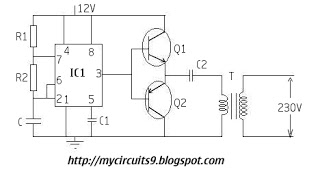
The timer IC (NE555) is configured as an astable multivibrator in this circuit. It generates an alternating non-sinusoidal output waveform as soon as a supply voltage of 12V is applied. Therefore, alternating voltage is produced from direct current (battery)....
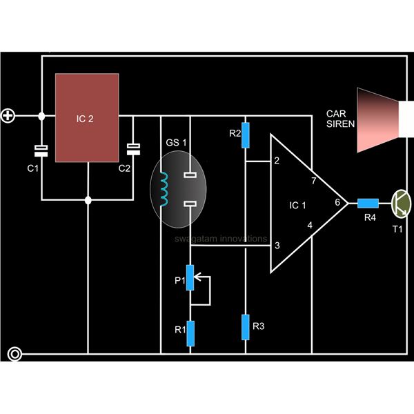
A straightforward smoke detector circuit has been presented through a schematic diagram, which can be easily constructed and installed in an area for essential detection purposes. The circuit utilizes the versatile FIGARO TGS 813 gas sensor as the primary...
An amplifier that utilizes either 211 or 845 vacuum tubes, delivering slightly over 40 watts of output power. To achieve this level of power, the tubes must operate in Class A2, which can be effectively managed with a suitable...
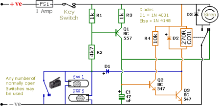
The schematic illustrates a Simple Motorcycle Alarm Circuit Diagram created by Ron J. It incorporates micro-switches to safeguard removable panels and... The Simple Motorcycle Alarm Circuit Diagram is designed to enhance the security of motorcycles by utilizing a series of...
The circuit is designed for conducting safe experiments with high-voltage pulses and operates similarly to an electrified fence generator. The pulse repetition frequency (PRF) is dictated by the time constant of the R1-C3 network within the feedback loop of...

This straightforward design of an inverter circuit is capable of delivering high output power with an efficiency of approximately 75%. It provides guidance on constructing an inverter that can meet most power requirements at a reasonable cost. The article...