
make a simple ic 741 smoke detector circuit schematic diagram enclosed
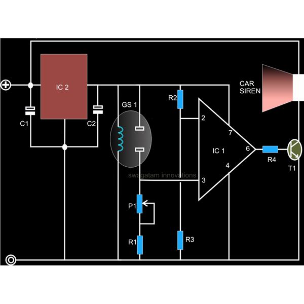
This smoke detector circuit is designed for simplicity and effectiveness in detecting smoke and potentially harmful gases. The FIGARO TGS 813 gas sensor operates by measuring changes in resistance when smoke particles are present in the air. This sensor is known for its sensitivity to a variety of gases, making it suitable for smoke detection applications.
The comparator stage, implemented with the operational amplifier IC 741, serves to compare the voltage level from the gas sensor with a reference voltage. When smoke is detected, the sensor's output voltage changes, causing the output of the comparator to switch states. This transition indicates the presence of smoke and can be used to trigger further actions.
The output from the comparator can be configured to control a relay, allowing for the integration of additional fire control systems, such as fire alarms or suppression systems. Alternatively, the output can be connected to a car siren or similar alarm device, providing an audible warning to alert individuals in the vicinity of the potential danger.
In constructing this smoke detector circuit, careful attention should be paid to the power supply requirements for the IC 741 and the gas sensor, as well as the characteristics of the relay or alarm device used. Proper calibration of the reference voltage at the comparator input may also be necessary to ensure reliable operation and sensitivity to smoke detection. Overall, this circuit offers a practical solution for smoke detection in various environments, enhancing safety and response capabilities.A very simple to build smoke detector circuit has been discussed here through a schematic diagram, which can be easily built and installed over an area for the necessary detection purposes. The circuit incorporates the versatile FIGARO TGS 813 gas sensor as the main sensing device. The detections made by the sensor is translated into a logic status through a comparator stage composed of the IC 741.
The generated warning signal is either integrated to a relay for triggering a fire control system or simply to a car siren for the required alarm.. 🔗 External reference
Related Circuits
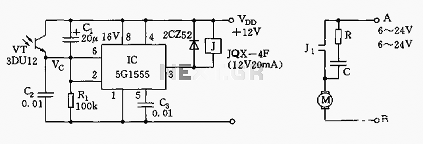
The control circuit consists of an NE555 timer and a phototransistor, along with resistors R1, capacitors C1 and C2, among other components. The photodiodes 3DU12 respond to sunlight by decreasing their resistance, which causes the voltage at the 555...

This circuit can be utilized in intercom systems, walkie-talkies, low-power transmitters, and packet radio receivers. Transistors T1 and T2 constitute the microphone preamplifier. Resistor R1 provides the necessary bias for the condenser microphone, while preset VR1 serves as a...

The IR photo transistor Q1 (Radio Shack 276-145A) or a similar component is connected to the set input (pin 6). It is essential to shield the photo transistor from direct light to ensure that the voltage at the set...
This is a basic Cadmium Sulfide (CdS) photocell detector circuit. In this circuit, when light falling on the photocell (PC1) is blocked, its resistance increases, causing the voltage across PC1 to rise. When the voltage exceeds half of the...

A single gate (open collector, non-inverting) generates a simple one-shot pulse that lasts for a duration equal to t, plus the RiCi time constant. R2 serves as a pull-up resistor to maintain the input of the gate high while...

The LM4819 audio power amplifier is designed to amplify audio signals. An audio signal is input through the coupling capacitor (Ci) and the resistor (Ri) applied to the inverting input terminal (pin 3) of the amplifier. The inverting input...