
60watt rf radio frequency
The 60 Watt RF amplifier circuit is designed for efficient amplification of radio frequency signals. The IRF840 MOSFET is the key component due to its high power handling capability and low on-resistance, which minimizes power loss during operation. The circuit operates at a supply voltage of 60V, drawing a current of 700 mA, which necessitates careful thermal management to prevent overheating of the MOSFET.
The choice of a dummy load is critical for testing the amplifier's performance. The use of a 24V 6 Watts bulb provides a manageable test load, while a 230V 60 Watts bulb can be used for higher power testing, ensuring that the amplifier can handle the desired output without distortion or damage.
The adjustment of the gate voltage is crucial for the stability and performance of the amplifier. The recommended gate voltage range of 0.8V to 1V helps to maintain the device within safe operating conditions, preventing self-oscillation that can lead to catastrophic failure.
The bifilar transformer T1 is a vital component that aids in impedance matching and signal coupling. The specific winding configuration of 8 turns of 26 SWG wire on a balun core ensures optimal performance at RF frequencies. The additional windings on the drain and the RFC contribute to the overall stability and efficiency of the amplifier, ensuring that it can operate effectively across a range of frequencies.
This amplifier design is suitable for various applications in RF transmission and can be integrated into more complex systems requiring RF signal amplification. Proper assembly and tuning of the circuit, along with adherence to the specified parameters, will yield reliable performance and longevity of the amplifier.The 60Watt RF (Radio Frequency) Amplifier is simple all solid accompaniment ambit application ability mosfet IRF840. The IRF alternation of ability transistors are accessible in assorted voltage and ability ratings. A distinct IRF840 can handle best ability achievement of 125 watts. Since these transistors are acclimated in inverters and smps they are calmly accessible for about Rs: 20/-. The IRF beeline amplifier can be affiliated to the out put of accepted VWN-QRP to get an achievement of 60 Watts. The ambit draws 700 ma at 60 Volt Vcc. Good calefaction bore is a charge for the ability transistor. Alignment of the ambit is actual easy. Connect a copy amount to the out put of the circuit. You can use some baby ball like 24V 6Watts as the copy load. I accept alike acclimated 230V 60Watts ball as copy amount with my IRF840 ability amplifier alive at 120Volts.
Adjust the 10K preset to get about 100 ma Cesspool current. I acclimated aboideau voltage of 0. 8V with my beeline amplifier. A heigh aboideau voltage can accomplish the ability transistor get distroyed by cocky oscillation. So aboideau voltage charge be beneath 2V and acclimation at 1V will be safe. Bifalar transformaer T1 is anguish with 8 turns 26SWG on 1. 4 x 1 balun core. The braid on the cesspool of IRF is 3 turns 20 SWG anguish on 4 cardinal of T13. 9 torroids (two torroids are ample to anatomy a balun core). The RFC at the Vcc band is 20 Turns 20 SWG anguish on T20 torroid. 🔗 External reference
Related Circuits
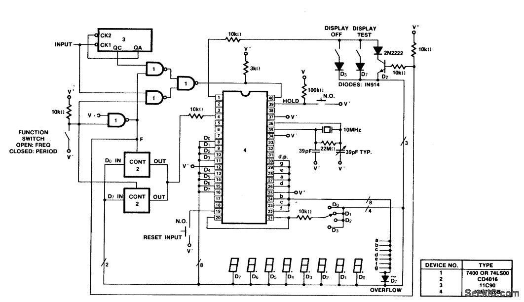
A 100 MHz frequency and period counter is constructed using the Intersil ICM7226B in a 40-pin DIP package. This circuit incorporates a CD4016 analog multiplexer to route the digital outputs back to the function input. The CD4016 operates as...
Capacitors are major electronic components classified as passive components. They are extensively used in electronic circuits, and virtually no circuit can be constructed without these essential parts. The primary function of a capacitor is to block direct current (DC)...
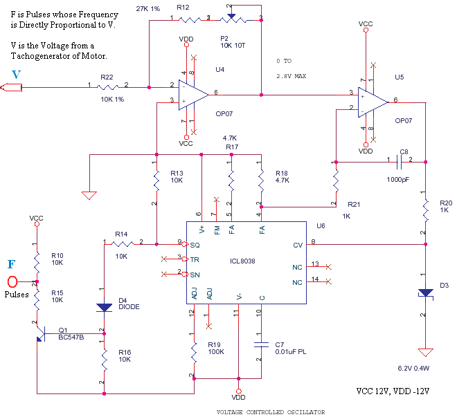
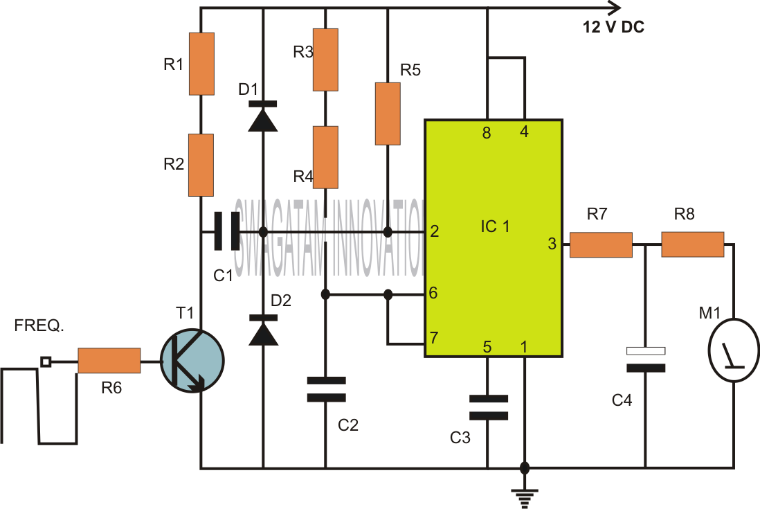
This is a small circuit designed to drive an impact counter, with the central component being the ICL8038. The circuit is intended for use with a motor that drives a conveyor, which includes a feedback mechanism known as a...
Building a foxhole radio is rewarding and the basic setup is very simple. It is, however, difficult to adjust, and it may take several attempts to find a proper razor blade for the detector. This is a project that...
This page is provided to the domain owner free by Sedo's Domain Parking. Disclaimer: The domain owner and Sedo maintain no relationship with third-party advertisers. References to any specific service or trademark are not controlled by Sedo or the...
This circuit illustrates the high and mid-frequency sections of a car radio. The medium wave band I operates within the frequency range of 520 to 950 kHz, while Poland II operates between 900 and 1640 kHz. The circuit employs...