
Arduino Button
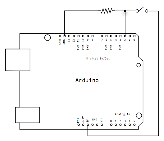
The circuit design involves connecting three wires to an Arduino board, facilitating the control of a pushbutton switch. The red wire is typically used to connect to the positive 5-volt supply, while the black wire connects to the ground (GND). These wires are routed to the vertical power rails on the breadboard, which distribute the voltage and ground throughout the circuit.
The third wire, connected to digital pin 2 on the Arduino, interfaces with one terminal of the pushbutton. The opposing terminal of the pushbutton is connected directly to the 5-volt supply, ensuring that when the button is pressed, the circuit is completed, allowing current to flow. A 10 KOhm pull-down resistor is connected from the same terminal of the pushbutton to ground. This configuration ensures that when the button is not pressed, the digital pin reads a LOW state because the resistor pulls the voltage down to ground level.
When the pushbutton is pressed, it creates a direct connection between the 5-volt supply and the digital pin, resulting in a HIGH reading. This behavior can be inverted by using a pull-up resistor instead, which would keep the input HIGH under normal conditions and switch to LOW when the button is pressed. This alternative configuration allows for flexibility in programming the behavior of the connected LED or other output devices.
It is crucial to avoid leaving the digital pin floating, as this can lead to unpredictable behavior in the circuit, such as erratic blinking of the LED. Implementing the pull-down or pull-up resistor stabilizes the input signal, ensuring reliable operation of the pushbutton interface within the Arduino project.Connect three wires to the Arduino board. The first two, red and black, connect to the two long vertical rows on the side of the breadboard to provide access to the 5 volt supply and ground. The third wire goes from digital pin 2 to one leg of the pushbutton. That same leg of the button connects through a pull-down resistor (here 10 KOhms) to grou nd. The other leg of the button connects to the 5 volt supply. When the pushbutton is open (unpressed) there is no connection between the two legs of the pushbutton, so the pin is connected to ground (through the pull-down resistor) and we read a LOW. When the button is closed (pressed), it makes a connection between its two legs, connecting the pin to 5 volts, so that we read a HIGH.
You can also wire this circuit the opposite way, with a pullup resistor keeping the input HIGH, and going LOW when the button is pressed. If so, the behavior of the sketch will be reversed, with the LED normally on and turning off when you press the button.
If you disconnect the digital i/o pin from everything, the LED may blink erratically. This is because the input is "floating" - that is, it will randomly return either HIGH or LOW. That`s why you need a pull-up or pull-down resistor in the circuit. 🔗 External reference
Related Circuits
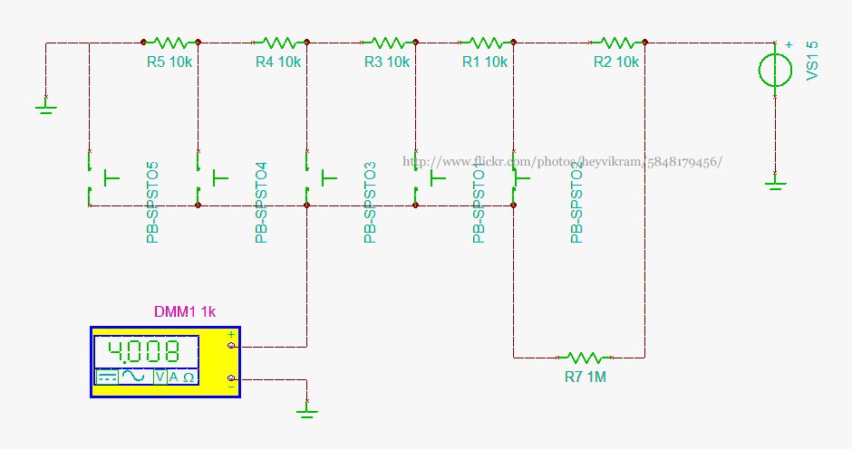
Connect a 5-way button/joystick to an Arduino using a single analog pin to quickly simulate it for verification of calculations before soldering. The voltages for the six states are 0, 1, 2, 3, 4, and 5. The 4V displayed...
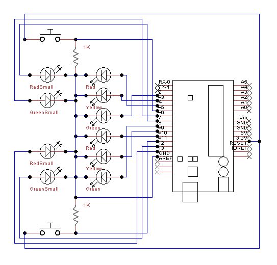
Set up the lights on the breadboard to resemble a traffic light configuration. The red LED should be positioned at the top, followed by the yellow LED, and then the green LED. The small red and green LEDs will...
The core of the circuit features an Arduino microprocessor, represented by the header pins on the left side of the circuit schematic. Two analog inputs, labeled 0 and 1, are connected to the emitter sides of TEMT6000 ambient light...
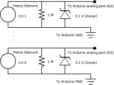
The piezo element is connected solely to Channel 1 (Arduino A[0] port). Channels 1 through 6 are linked to female mono jacks, with the ground (GND) wiring arranged in series from jacks 1, 2, and 3, continuing to the...
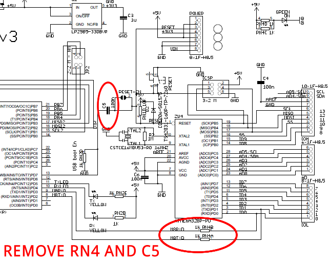
The Arduino Uno is a simple modification that bypasses the USB circuitry, allowing the device to be programmed using a serial port. The Arduino Uno is a widely used microcontroller board based on the ATmega328P microcontroller. It is designed to...

The USB to RS232 converter is called USB-2-bot and comes from another project. Any other converter would work as well, e.g. this USB-TTL-232-cable from adafruit. It has an ISP connector to program the bootloader and a serial connection used...