
DC 12V Battery Charger Circuit Schematic
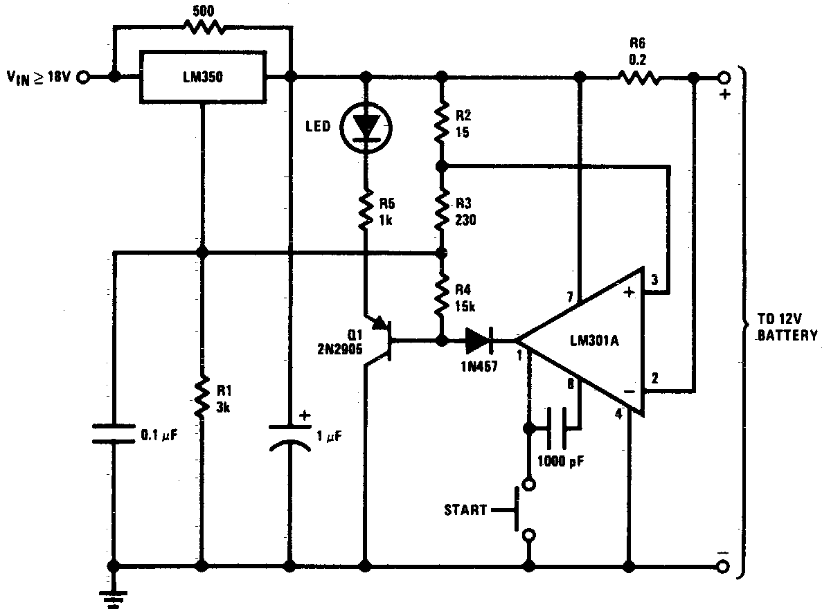
The DC 12V battery charger circuit is designed to efficiently charge gelled electrolyte lead-acid batteries, which are commonly used in various applications due to their reliability and performance characteristics. The circuit typically consists of several key components: a transformer, a rectifier, a filter capacitor, a voltage regulator, and various protection elements such as diodes and fuses.
The transformer steps down the AC mains voltage to a lower AC voltage suitable for charging the battery. The rectifier, often implemented with diodes, converts the AC voltage to pulsating DC. The filter capacitor smooths the output from the rectifier, providing a more stable DC voltage to the battery.
A voltage regulator may be included to ensure that the output voltage remains constant and within safe limits for the battery being charged. This is critical to prevent overcharging, which can damage the battery and reduce its lifespan. Protection components, such as fuses, are incorporated to safeguard the circuit against overcurrent conditions, while diodes can be used to prevent reverse current flow from the battery back into the charger.
The design may also incorporate a charging indicator, such as an LED, to visually indicate the status of the charging process. Overall, this circuit provides a reliable and efficient solution for charging gelled electrolyte lead-acid batteries, ensuring optimal performance and longevity.DC 12V Battery Charger Circuit Diagram. This circuit is a high performance charger for gelled electrolyte lead-acid batteries.. 🔗 External reference
Related Circuits
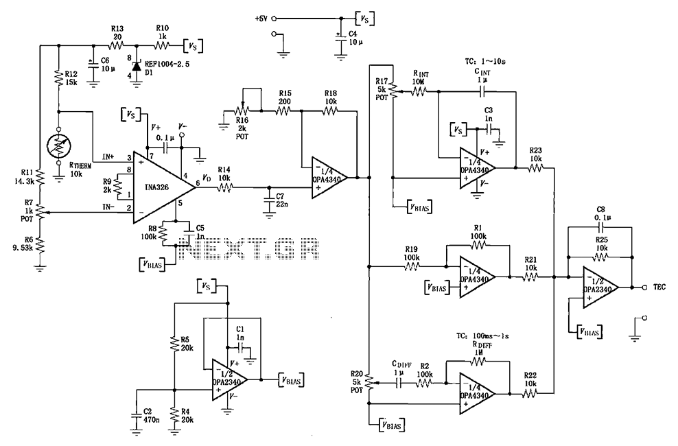
The INA326/327 forms a single power PID (proportional-integral-derivative) controller as illustrated in the temperature control loop. This circuit is primarily designed for temperature measurement and control. A thermistor, designated as RTHERM, detects temperature changes and converts them into an...
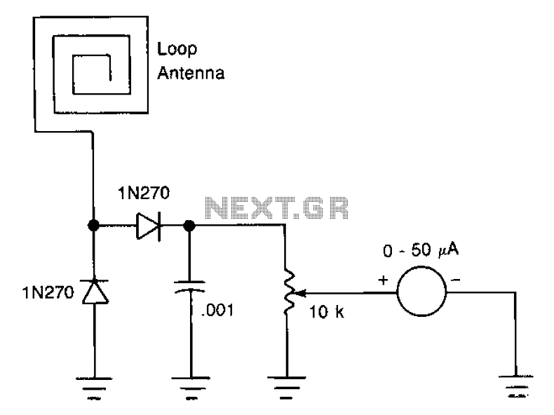
The antenna consists of approximately 20 cm of insulation made from strands, which are glued together inside a small plastic box. An RF current is processed through two diode rectifiers, and a 10k potentiometer is connected to the pin...
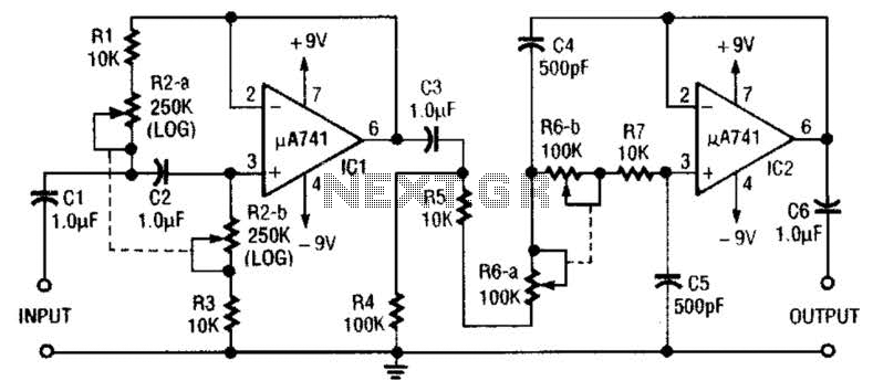
This circuit is a variable audio bandpass filter that features a low cutoff adjustable from approximately 25 Hz to 700 Hz and a high cutoff adjustable from 2.5 kHz to over 20 kHz. The roll-off is set at 12...
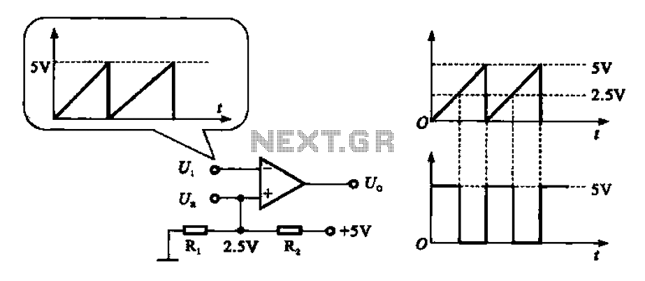
The addition and subtraction functions of an operational amplifier are facilitated through an external feedback network, which places the integrated operational amplifier in a deep state of negative feedback. In this linear region, the relationship between input and output...
The LED flasher circuits operate on a single 1.5-volt battery. The circuit on the upper right utilizes the popular LM3909 LED flasher IC and requires only a timing capacitor and an LED. The LED flasher circuit using the LM3909 integrated...
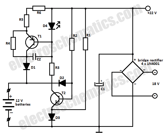
This battery charger circuit is designed to charge one or more batteries with a total nominal voltage of 12 V, which accommodates either ten NiCd batteries or six 2 V lead-acid batteries. The battery charger circuit operates by utilizing a...