
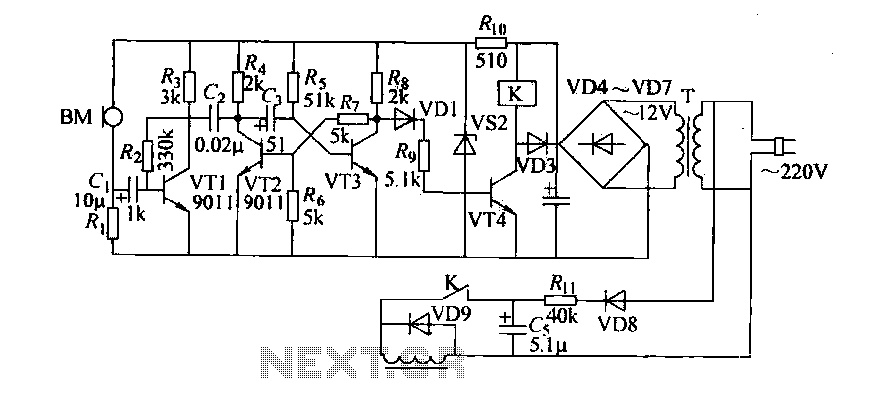
12V Battery Charger Circuit
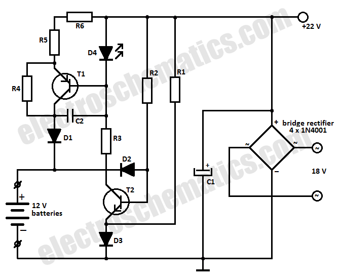
The battery charger circuit operates by utilizing a voltage regulator and a suitable charging algorithm to ensure safe and efficient charging of the batteries. The circuit typically consists of a transformer, rectifier, filter capacitor, and a voltage regulator, which together convert the AC mains voltage to a stable DC output suitable for battery charging.
In a standard configuration, the transformer steps down the AC voltage to a lower level, which is then rectified by a diode bridge to convert the AC voltage to pulsating DC. A filter capacitor smooths out the rectified voltage, providing a more stable DC output. The voltage regulator, often a linear regulator or a switching regulator, maintains the output voltage at the desired level, compensating for variations in input voltage and load conditions.
For charging NiCd batteries, the circuit may include additional features such as a constant current source to prevent overcharging and a temperature sensor to monitor battery temperature during the charging process. This ensures that the batteries are charged safely and efficiently without the risk of thermal runaway or damage.
When charging lead-acid batteries, the circuit may incorporate a multi-stage charging process, including bulk charging, absorption charging, and float charging phases. This method helps to optimize the charging process, prolong battery life, and enhance performance.
In summary, this battery charger circuit is versatile and can accommodate various battery types, making it suitable for applications requiring reliable battery charging solutions. Proper design considerations and components selection are crucial for ensuring the circuit's efficiency and safety during operation.This battery charger circuit can be used to charge one or more batteries with the total nominal voltage of 12 V, meaning ten NiCd battery or six 2 V lead a.. 🔗 External reference
Related Circuits
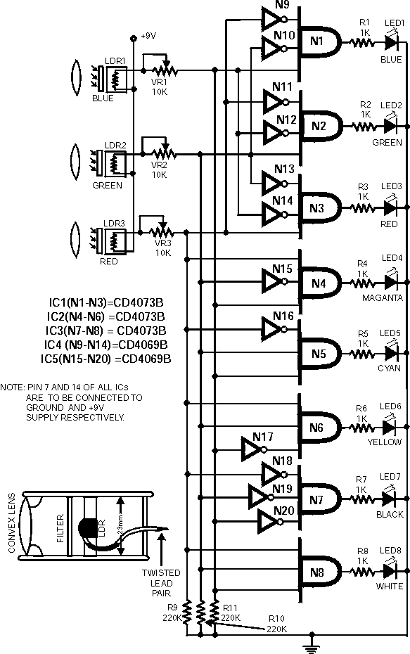
Colour sensor is an interesting project for hobbyists. The circuit can sense eight colours, i.e. blue, green and red (primary colours); magenta, yellow and cyan (secondary colours); and black and white. The circuit is based on the fundamentals of...
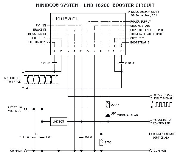
These circuits could be used as the basis for Model Railroad DCC Boosters or PWM motor controllers. The first schematic is for a basic 3 Amp - DCC Booster using the LMD 18200 CMOS, H-Bridge. Included in the design...
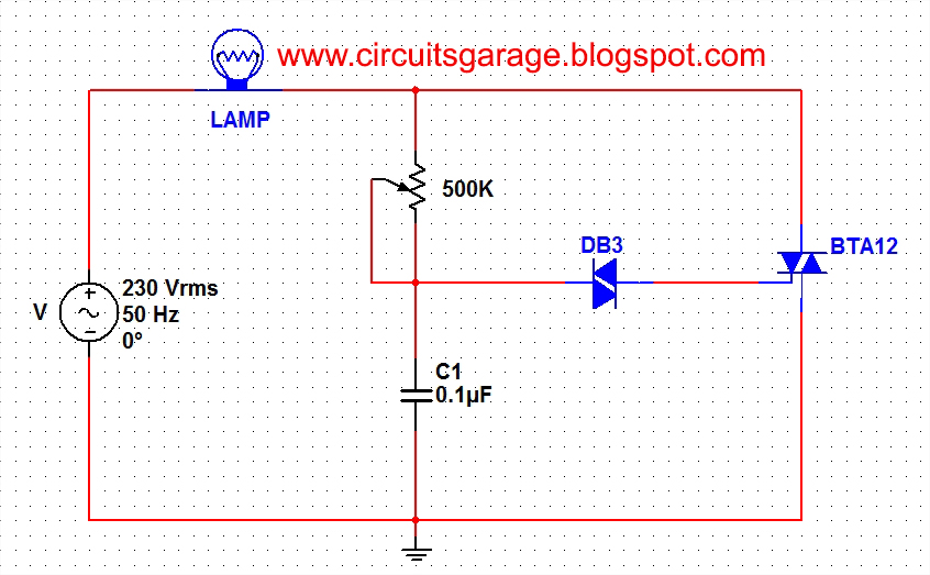
A light dimmer circuit is used to adjust the illumination of a lamp. The following circuit illustrates a basic TRIAC triggering circuit that utilizes a DIAC. In this circuit, the illumination of the light is regulated through the interaction...
Cook in advance to open the door with a coal stove; before using the fire, it should be strong. This is an automatic door opening device that can automatically open the door before the regular homeowner, eliminating the need...
The series consists of input buffers that match the output. This configuration resembles a common collector circuit with a reinforcement factor of 1. A resistor value is included to limit the current usage. The effectiveness of this circuit largely...
The circuit illustrates a two-stage voltage amplifier that drives a recording level meter. An AC signal input is amplified and rectified, with the resulting DC voltage displayed on the meter. This circuit is compatible with tape recorders or audio...