
Discrete PWM Generator Circuit
PWM (Pulse Width Modulation) waveforms are essential in controlling the speed of DC motors due to their ability to vary the effective voltage supplied to the motor. The mark/space ratio, which determines the average power delivered to the motor, can be adjusted using either an analog voltage level or digital binary inputs. In applications where microcontrollers are not used, discrete logic components can efficiently generate PWM signals.
The circuit described can produce two PWM outputs from an 8-bit digital input. Each output can represent 15 different duty cycle values, allowing for fine control over motor speed. This is particularly useful in systems where precise motor control is necessary, such as robotics or automated machinery. The 8-bit input may originate from various sources, including a PC expansion board or a processor with limited PWM capabilities.
In the schematic, a binary input of 0000 results in both outputs being low, effectively stopping the motors. This feature simplifies the design, as an additional enable input is not required. The use of the HCF4060 integrated circuit as a clock generator allows synchronization of the PWM signals, ensuring that both channels operate in harmony.
The 74HC193 counter is critical for extending the circuit to produce two PWM signals. The integration of a flip-flop from the 74HC74 package provides additional functionality, enabling the second PWM channel. The design showcases an efficient use of components, requiring only four ICs to achieve dual PWM outputs, making it a compact solution for applications demanding dual motor control. Overall, this circuit exemplifies a practical approach to PWM signal generation using discrete logic components, suitable for a variety of electronic projects.PWM waveforms are commonly used to control the speed of DC motors. The mark/space ratio of the digital wave-form can be defined either by using an adjustable analogue voltage level (in the case of a NE555 based PWM generator) or digitally using binary values. Digitally derived PWM waveforms are most often produced by the timer/counter modules in m icrocontrollers but if you do not want to include a microcontroller in your circuit it`s also quite simple to generate the signals using discrete logic components. An extension of the circuit shown can produce two PWM wave-forms from an 8-bit digital input word. Each signal has 15 values. The 8-bit word can be produced for example from an expansion board fitted in a PC or from an 8-bit port of a processor which does not have built-in PWM capability or from a laptop`s printer port.
The mark/space ratio is only programmable up to 15/16 rather than 16/16; a binary input of 0000 produces a continuous low on both outputs turning both motors off. Similar circuits often employ a dedicated enable` input to turn the motors off but it is not necessary in this design.
The diagram shows the circuitry required to produce just one waveform. For the full two channel circuit it is necessary to use an additional 74HC193. The clock signal produced by the HCF4060 generator can be used to drive both channels and the free flip flop in the 74HC74 package can be used for the second channel (the corresponding pin numbers are shown in brackets). Altogether the entire two channel circuit can be built using just four ICs. 🔗 External reference
Related Circuits
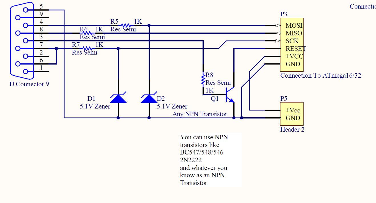
ISP programmer with circuit diagram for AVR Atmega32 microcontroller. This ISP burner circuit is an adaptation of the Pony programmer and uses PonyProg software. The ISP (In-System Programming) programmer designed for the AVR Atmega32 microcontroller facilitates the programming of the...
Bidirectional control is implemented for a motor to increase its operational degree. The motor can rotate in either direction with a current of 1A. A variable duty cycle multivibrator is utilized to achieve the construction and control of the...
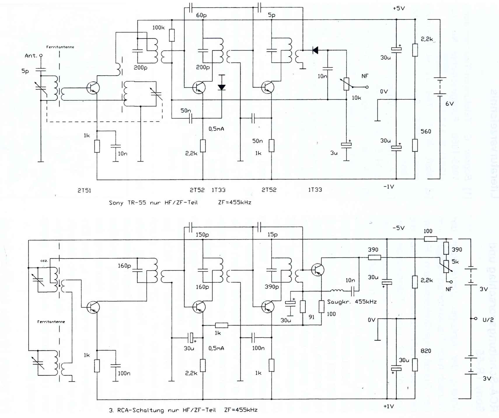
The circuitry of the Regency exhibits several unique characteristics. Notable features include the self-oscillating mixer stage, the base bias voltage of the second IF stage derived from the AF power stage, an unusual IF frequency of 262 kHz, and...
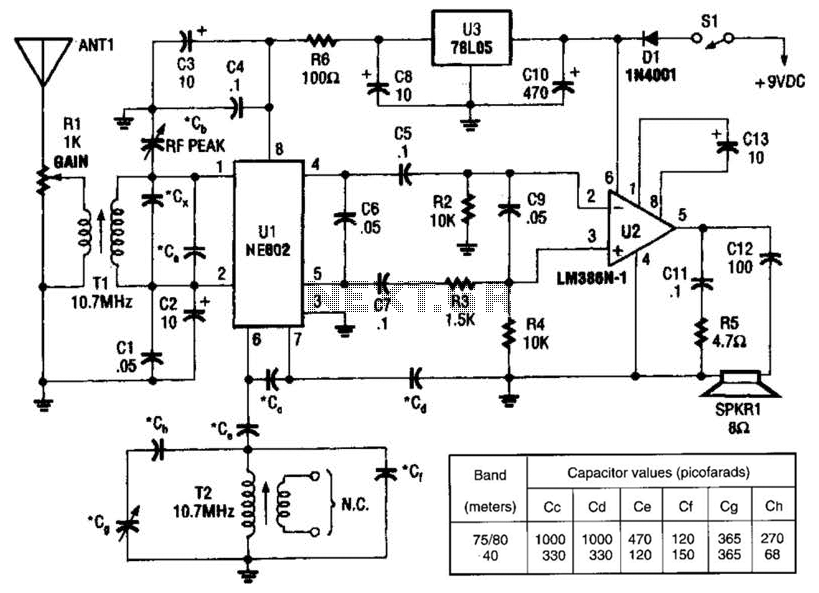
An NEC602 is utilized as a mixer with a zero intermediate frequency (IF) output, while U2 functions as an audio amplifier. This receiver is mainly designed for single sideband (SSB) and continuous wave (CW) signals. T1 and T2 are...
This circuit generates the power required to operate a bipolar stepper motor. It allows for adjustments in both the rotation speed and direction of the motor. The design includes two integrator circuits (A1, A3) and an amplifier (A2) connected...
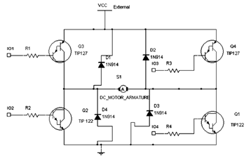
The diagram below illustrates an H-Bridge circuit featuring four inputs and an external power supply. The control application must enable the motor to operate in both forward and reverse directions. The H-Bridge is a crucial component in motor control applications,...