
High voltage generator circuit
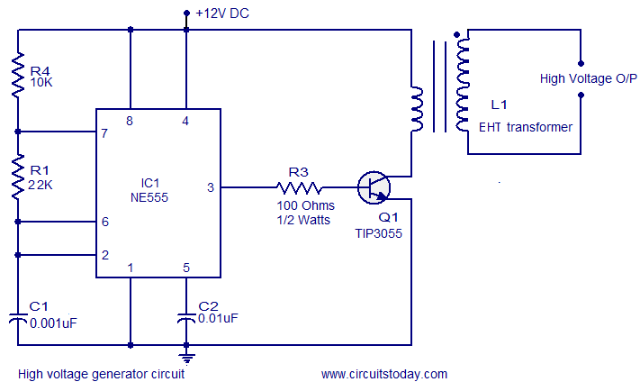
The circuit design encompasses three critical components: the oscillator, the switching stage, and the step-up transformer. The oscillator, based on the NE555 timer, generates a square wave signal at a frequency of 25 kHz. This frequency is essential for the subsequent stages of the circuit, as it determines the operating frequency of the entire system.
The NE555 timer is configured in astable mode, producing a continuous output signal that toggles between high and low states. This output is connected to the base of the TIP3055 power transistor, which serves as a switch. The TIP3055 is a high-power NPN transistor capable of handling significant current, making it suitable for this application. When the NE555 timer outputs a high signal, the TIP3055 is turned on, allowing current to flow through the primary winding of the step-up transformer.
The step-up transformer plays a vital role in this circuit by increasing the voltage from the primary side to the secondary side. The transformer is designed to operate at the same frequency as the oscillator, ensuring efficient energy transfer. As current flows through the primary winding, a magnetic field is established, which induces a high voltage in the secondary winding due to the transformer's turns ratio.
Safety precautions must be emphasized when working with this circuit. Proper insulation, protective equipment, and adherence to safety protocols are essential to prevent electric shock or other hazards. This circuit should only be constructed and tested in a controlled environment by individuals with adequate knowledge of high-voltage systems.First of all let me remind you that this circuit is a very dangerous one. The output voltage of this circuit is in Kilo volts and it can seriously injure you or kill you. Try this circuit only if you have enough experience dealing with high voltages. I have no responsibility on any hazards caused by the circuit. Be very careful. This is a humble r equest. The circuit given here has three sections namely oscillator, switching stage and a step up stage. The oscillator is build around a NE555 timer operating at 25 KHz. The output of the NE555 coupled to the base of the power transistor TIP3055 which is the switching device. The power transistor drives primary of the step up transformer at 25 KHz and as a result a high voltage will be induced across its secondary.
🔗 External reference
Related Circuits
A substation capable of consuming 100 MVA with 375 kVA, 60 Hz input and 132 kV at 50 Hz using the same power. The challenge is to convert the 60 Hz input to 50 Hz, including a wiring diagram. To...
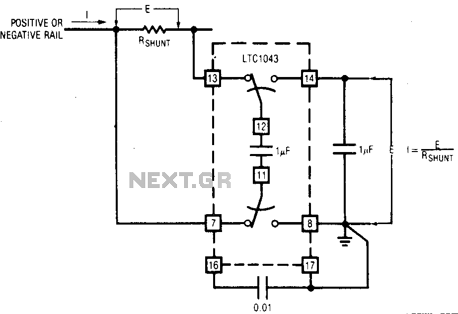
The LTC1043 can be induced through any of its current shunt supply rails. Many cells and solar system applications have this feature. If the reference point is grounded, the voltage output of an unloaded amplifier is minimal, allowing the...
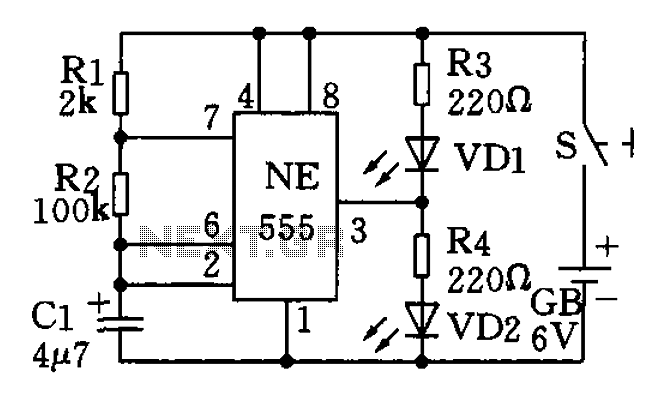
The circuit utilizes a 555 timer as the central component of a flashing light circuit. In normal operation, the light-emitting diodes (LEDs) VD1 and VD2 alternate flashing. The circuit comprises the NE555 timer, resistors R1 and R2, and capacitor...
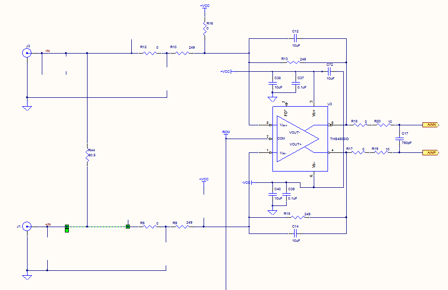
Prior to the test point, there is an AD744 operational amplifier with its output connected to a 10nF capacitor. Following this, a 1kΩ resistor connects to ground. From the junction where the capacitor and resistor meet, a 4.7kΩ resistor...
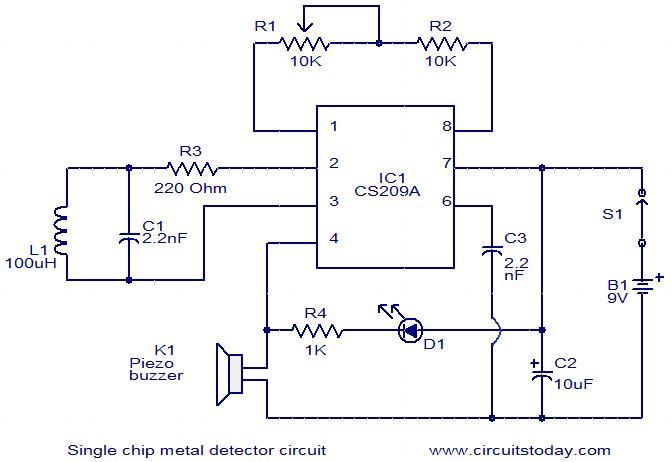
This is a simple single-chip metal detector circuit based on the IC CS209A from Cherry Semiconductors. A 100µH coil is utilized to detect the presence of metal. The IC CS209A incorporates a built-in oscillator circuit, with the coil (L1)...
The circuit is straightforward, utilizing a single IC chip, the ICL8038 function generator chip, which produces simultaneous sine, square, and sawtooth waveforms. The circuit consists of a minimal number of components, including two resistors, one transistor, five trimpots, and...