
voltage converter circuit diagram
To convert a 60 Hz power supply to a 50 Hz output in a substation, a frequency converter is required. The frequency converter typically consists of a rectifier, a DC link, and an inverter. The rectifier converts the 60 Hz AC input voltage to a DC voltage. The DC link stabilizes the voltage and allows energy storage, which can help in maintaining a steady output during fluctuations. Finally, the inverter converts the DC voltage back to AC at the desired frequency, which in this case is 50 Hz.
The schematic for the substation would include the following key components:
1. **Input Transformer**: The input transformer steps down the 132 kV supply to a more manageable voltage level suitable for the rectifier. It is crucial to select a transformer that can handle the power requirements of 100 MVA.
2. **Rectifier**: A three-phase diode bridge rectifier is commonly used for converting the AC input (60 Hz) to DC. This component must be rated for the maximum current and voltage expected from the transformer output.
3. **DC Link**: This section typically includes capacitors to smooth the DC voltage output from the rectifier. The capacitance value should be calculated based on the load requirements and expected ripple voltage.
4. **Inverter**: The inverter is responsible for converting the DC voltage back to AC at 50 Hz. A PWM (Pulse Width Modulation) inverter is often employed for this purpose, providing better control over the output waveform and allowing for more efficient operation.
5. **Output Transformer**: After the inverter, an output transformer may be used to step up the voltage back to 132 kV, if necessary, for distribution purposes.
6. **Control System**: A control system is essential for managing the operation of the frequency converter, ensuring synchronization between the input and output, and providing protection against faults.
7. **Wiring Diagram**: The wiring diagram should clearly illustrate the connections between these components, including the input and output terminals, grounding points, and any necessary protection devices such as circuit breakers or fuses.
This comprehensive approach ensures that the substation can efficiently convert the frequency from 60 Hz to 50 Hz while maintaining the required power output of 100 MVA. Proper attention to component ratings and system design will be crucial for reliable operation.A substation capable of consuming 100MVA with375KVA, 60Hz in input and 132KV and 50hz using same power. so my problem is how to change the 60hz to 50hz, including wiring diagram 🔗 External reference
Related Circuits
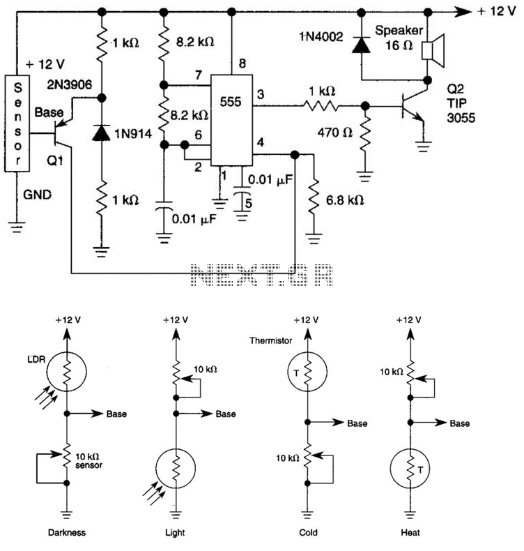
The tone generated by a 555 oscillator can be activated by heat or light, which causes Q1 to conduct transistor Q2 (TIP 3055). Q2 (TIP 3055) functions as an audio amplifier and speaker driver. The circuit utilizes a 555 timer...
The mixer features two stereo phono inputs and two stereo line-level inputs, along with one stereo bonded channel. It also includes a microphone input and a stereo output with adjustable gain. The mixer is designed to accommodate a variety of...
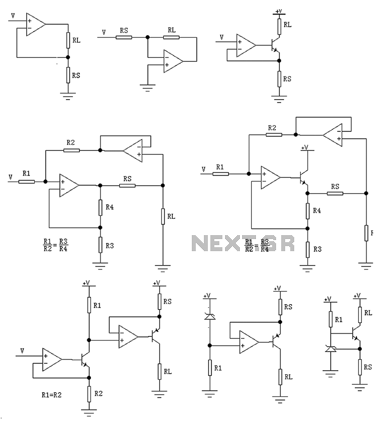
The circuit is designed to provide several constant current outputs to the load resistor RL. The first RL is floating and is rarely utilized. The second RL serves as a virtual ground and is not commonly used either. The...
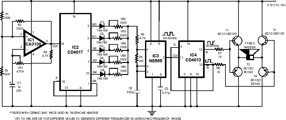
There are many ultrasonic pest repellent devices available on the market, but a major drawback is that their power output is low and their effectiveness suffers. Ultrasonic pest repellent devices utilize high-frequency sound waves to deter pests such as rodents...
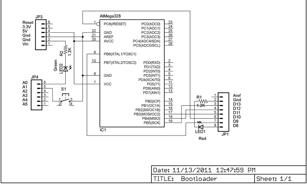
This Lazy Old Geek is also an Arduino enthusiast. One of the common microcontrollers used by Arduinos is the Atmega328 chip. To utilize Arduino software, the Atmega must be equipped with bootloader software. There is a notable difference between...
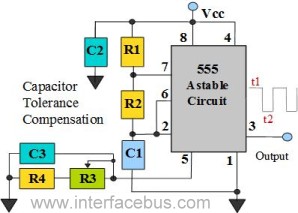
The 555 Timer is configured as an astable multivibrator. Additional components have been incorporated to enhance circuit operation. Upon powering the circuit, the 555 Timer will generate a square wave, determined by the values of Capacitor C1 and Resistors...