
Pwm Motor Speed Control Circuit With Diagram For Dc

No description available.
Related Circuits
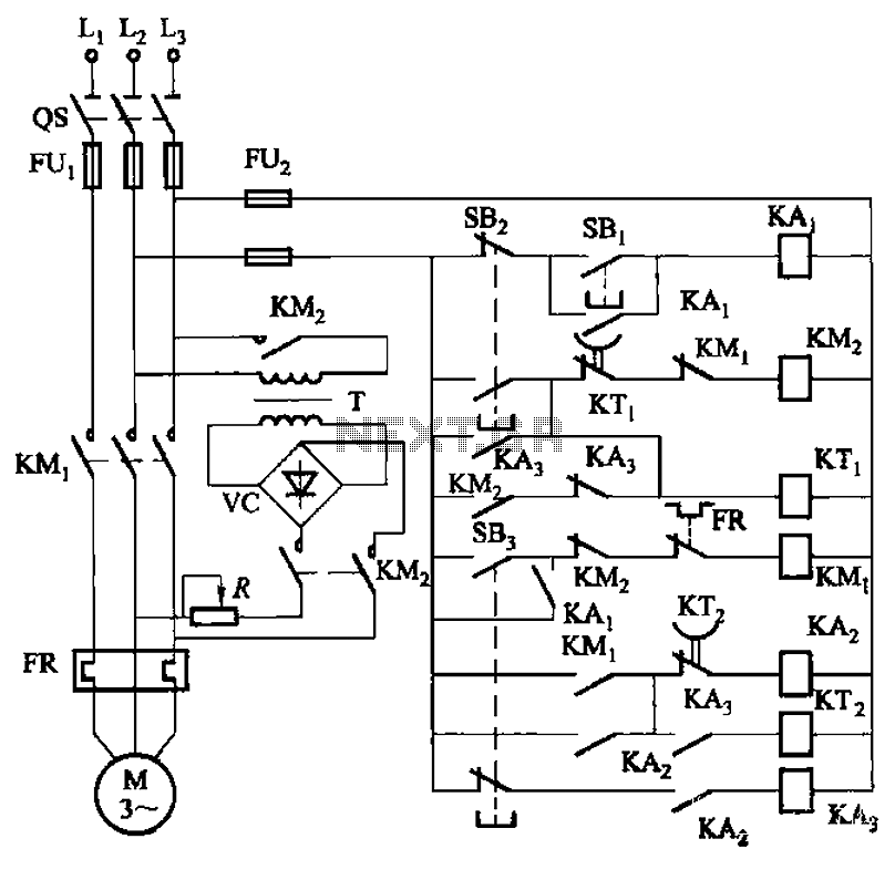
The circuit depicted in Figure 3-143 demonstrates a braking mechanism for a motor that operates effectively during normal shutdown and jog operations. The circuit includes several components, such as the start button (SBz), stop button (SBz), and jog button...
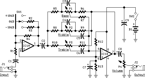
The IC1A operational amplifier is configured as an inverting amplifier, with its gain determined by a three-way switch that connects different resistor values in parallel to R4. Following this input stage is an active three-band tone control circuit, designed...
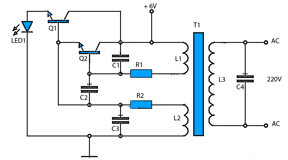
The circuit schematic presented is a voltage inverter circuit that converts a 6-volt DC input into a 220-volt AC output. It is designed to deliver a maximum output power of 30 watts and operates with a low input current....
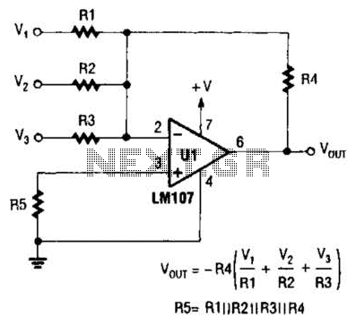
The output of Ul is the sum of Vv, multiplied by the ratio of Rx to Rv, RJRV, and respectively. Resistors R1, R2, and R3 are selected as required for individual gains. Additionally, R4 influences the gain of all...
Laser Command is a game developed using an 8x8 matrix LED and an Arduino Mini. It was created as a sample class project in the Gadgets, Sensors, and Activity Recognition course at Carnegie Mellon University, taught by Scott Hudson....
This continuous wave (CW) transmitter is capable of producing an output power of up to 3 watts. By applying a 24-volt supply to transistor Q2, the output power can be increased to as much as 10 watts. It is...