
laser command circuit
The first technique utilizes LEDs as light sensors. In this method, LEDs are charged by applying reverse bias, and the discharge rate of the current is measured once the reverse bias is removed. The time taken for the LEDs to discharge is inversely proportional to the brightness of the light. If D0 quickly goes LOW, it indicates that one or both of the top row LEDs are illuminated by the laser pointer. Similarly, if D1 goes LOW quickly, it signifies that the bottom row LEDs are targeted by the laser pointer. This technique is effective for a single LED but insufficient for identifying columns in a matrix LED configuration, as LEDs in the same row share a cathode.
The second technique, which is less common due to its requirement for analog inputs, involves measuring the voltage generated by charged LEDs when exposed to strong light. In this circuit, the voltage rises from approximately 0.5V to 1.5V when a laser pointer is aimed at an LED. While this voltage is not high enough for a digital input to register as HIGH, it can be detected using analogRead(). This allows for the identification of which column is illuminated by the laser pointer. By alternating between these two techniques, it is possible to determine the exact LED being targeted.
The accompanying circuit diagram represents an 8x8 matrix LED configuration based on the previously mentioned 2x2 example. In this circuit, analog ports A6 and A7 are connected to digital ports D11 and D12, respectively, as these ports do not function as digital outputs. The design requires eight analog inputs, necessitating the use of an Arduino Mini, Nano, or Mega, or any other compatible board with more than eight analog ports. Slight modifications enable the use of an Arduino Duemilanove for a 8x5 matrix LED configuration.
The code provided serves as a sample demonstrating the use of an 8x8 matrix LED as a light sensor array and the detection of the position of an LED illuminated by a laser pointer. The wiring configuration assumes that digital ports D2 to D9 are connected to the cathodes, while analog ports A0 to A7 connect to the anodes. Digital ports D11 and D12 are linked to A6 and A7, respectively. Detailed circuit diagrams provide further clarification on the connections. Upon powering the circuit, all LEDs illuminate sequentially, followed by the activation of the LEDs targeted by the laser pointer.Laser Command is a game which I build using a 8x8 matrix LED and an Arduino Mini. This game was developed as a "sample" class project in S10-05833 Gadgets, Sensors and Activity Recognition in HCI. The class is taught by Scott Hudson at Carnegie Mellon University, and I`m doing TA for the class. The name "Laser Command" comes from an old game called Missile Command. In Missile Command, you are asked to shoot enemy`s missiles using missiles. In Laser Command, you shoot using laser, i. e. , a laser pointer. The most interesting part in this game is that the game uses a laser pointer as a two-dimensional input device in conjunction with a matrix LED. Here are a video, explanations of how it works, circuit diagrams and source code. I hope that these are enough for you to replicate and/or build on the technique :) In the followings, I will explain how the two techniques work using a simplified example shown below.
The example consists of two digital ports (D0 and D1), two analog ports (A0 and A1) and four LEDs, i. e. , a 2x2 matrix LED. The first technique is well-known technique for using LEDs as light sensors. In this technique, we charge LEDs by applying reverse bias, and, then, measure how quickly the charged current leaks after stopping the reverse bias.
In the example here, the technique works as follows: The time required for the leakage to discharge the LEDs is inversely proportional to the brightness. So, if D0 becomes LOW quickly, we can know that one of (or both) the LEDs at the top row is pointed by a laser pointer.
Likewise, if D1 becomes LOW quickly, the LEDs at the bottom row are pointed by a laser pointer. This technique is sufficient if we just want to use a single LED as a light sensor. But, it is not sufficient if we want to use a matrix LED as a light sensor array. As described above, we can detect which row is pointed by a laser pointer, but we cannot distinguish which column is pointed because LEDs at the same row share a cathode. The second technique is not commonly used because it requires analog inputs. When we project strong light on LEDs, the LEDs are charged. In this technique, we directly measure the voltage generated by the charged LEDs as follows: In my circuit, the voltage rises from 0.
5V to 1. 5V (this value depends on LEDs) when the LED is pointed by a laser pointer. This is not enough for digital input to become HIGH. But, the difference can be detected by analogRead(). Using this technique, we can detect which column is pointed by a laser pointer. Therefore, by using these two technique by turns, we can detect which LED is pointed. Here is a circuit diagram which you can use with sensor sample source code. The circuit is a 8x8 matrix LED version of the example (2x2 version) discussed above. In the circuit, A6 and A7 are connected to D11 and D12 receptively. This is because these two ports do not work as digital outputs. This circuit requires eight analog inputs, so that you need an Arduino Mini, Nano or Mega (or whatever which supports more than eight analog ports). If you use an Arduino Duemilanove, you still can make a 8x5 matrix LED as a light sensor array with slight modifications.
// // Using a Laser Pointer and a 8x8 Matrix LED // as Two-dimensional Input device // Developed Eiji Hayashi // 2010/03/26 Version 1. 0 // // * What`s this * // This is a sample code which shows how we can use // a 8x8 matrix LED as a light sensor array, and // how we can detect position of a LED pointed by // a laser pointer.
// // * Wiring * // This code assumes: // D2 to D9 are connected to cathodes // A0 to A7 are connected to anodes // D11 and D12 are connected to A6 and A7 respectively // Please refer to circuit diagrams for more details. // // * How it works * // When you turn on a circuit, all LEDs turn on one-by-one. // After that LEDs pointed by a laser pointer turn on. // #include
Related Circuits
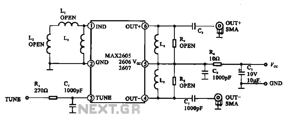
A low phase noise voltage-controlled oscillator circuit is presented, specifically integrated within the MAX2605-2609 voltage-controlled oscillator series. The circuit features a tuning voltage control terminal, allowing for adjustable oscillation frequency through a DC voltage input. The output of the...

The circuit is designed to regulate a dual power supply that provides +12V and -12V from the AC mains. Such a power supply is an essential tool for an electronic hobbyist's workbench. The schematic of the circuit includes components...
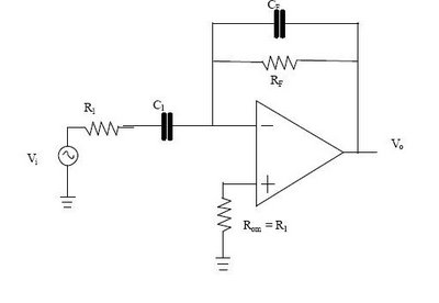
The differentiator circuit is an application circuit derived from mathematical principles influenced by capacitor behavior. The circuit, as illustrated in the accompanying image, is a simple differentiator configuration. To derive the differentiator formula, the following sequence is used: Ic...
Most 24V power systems in trucks, 4WDs, RVs, boats, and similar applications utilize two series-connected 12V lead-acid batteries. The charging system is capable of maintaining the total voltage of the individual batteries. If one battery is experiencing failure, this...
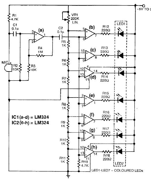
This sound level meter circuit can be used to control the intensity of a sound recording or in a disco. It has 5 measurement domains between 70 and 120 dB. The sound level meter circuit is designed to measure sound...
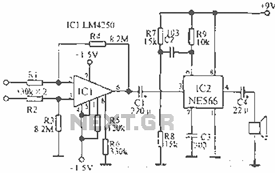
The circuit is designed for teaching demonstrations or experiments to hear the electrocardiogram (ECG) signal voltage. The ECG signal voltage is amplified by the LM4250 operational amplifier, which is connected to a voltage-controlled oscillator (NE566) to modulate the oscillator...