
SINGLE TRANSISTOR CODE PRACTICE OSCILLATOR
The circuit utilizes a 2N366 transistor, which is a general-purpose NPN transistor, serving as the primary active component in the audio feedback oscillator configuration. The audio transformer plays a crucial role in coupling the output signal back to the input, thereby creating the feedback necessary for oscillation.
In this setup, the audio transformer is connected to the collector of the 2N366, allowing the amplified audio signal to be fed back into the base of the transistor. This feedback mechanism is essential for sustaining oscillations at a frequency determined by the values of the surrounding components, including resistors and capacitors.
The resistor R1 is particularly important as it adjusts the biasing of the transistor. By varying R1, one can control the gain of the circuit and, consequently, the frequency of the audio oscillation. A lower resistance value typically allows for a higher gain, resulting in a higher frequency output, while a higher resistance value reduces the gain and lowers the frequency.
The output of the circuit can be taken from the secondary winding of the audio transformer, which can be connected to a speaker or an audio processing unit, allowing for sound generation. Proper tuning of R1 is critical to achieve the desired audio note, which can be used in various applications such as sound effects, alarms, or as part of a larger audio system.
Overall, this simple yet effective circuit demonstrates the principles of feedback and oscillation in audio applications, showcasing the versatility of the 2N366 transistor in generating sound through electronic means.A 2N366 is configured as an audio feedback oscillator using an audio transformer is shown. Adjust R1 for proper operation and desired audio note.. 🔗 External reference
Related Circuits
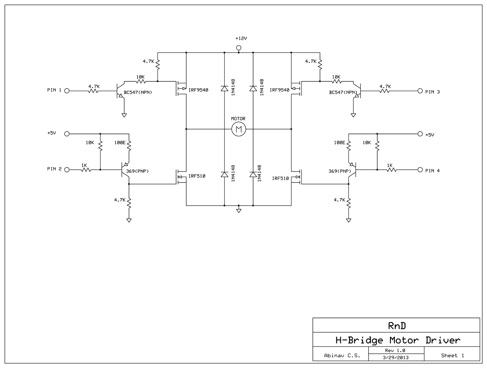
This post discusses the construction of an H-Bridge Motor Driver circuit using simple MOSFETs and transistors. The primary feature of this H-Bridge is its ability to drive a motor in both directions. An H-Bridge is a circuit that allows...
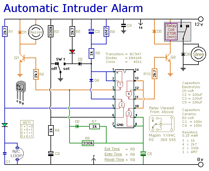
This is a simple single-zone home alarm system circuit. Its features include entry delays, a timed siren cut-off, and automatic exit. It is designed to be used with the usual types of normally-closed input devices such as foil tape,...
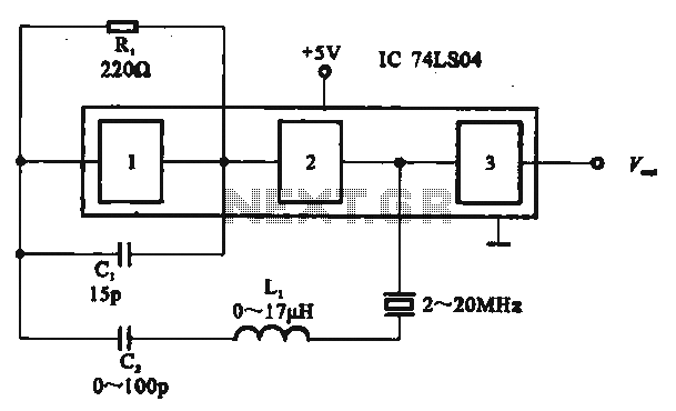
The circuit includes several gates arranged as a crystal oscillator circuit. Figure (A) illustrates a crystal oscillator circuit operating at 1 MHz, while Figure (B) depicts a 20 MHz crystal oscillator circuit. Figure (C) represents a variable crystal oscillator...

Bipolar transistor amplifiers must be properly biased to operate correctly. In circuits made with individual devices (discrete circuits), biasing networks consisting of resistors are commonly employed. More elaborate biasing arrangements are used in integrated circuits, such as bandgap voltage...
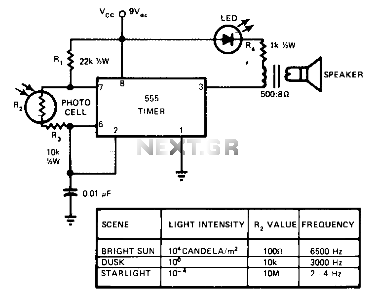
This circuit's frequency of oscillation increases directly with light intensity. The greater the light intensity, the higher the frequency of the oscillator. The 555 timer operates in the astable oscillator mode where frequency and duty cycle are controlled by...
A question has been raised regarding the type of oscillator found on Wikipedia, specifically referring to the NPN Colpitts oscillator as illustrated in the image titled "File:NPN Colpitts oscillator collector coil.png." The NPN Colpitts oscillator is a type of electronic...