
Simple Electronic Fan Regulator Circuit PCB
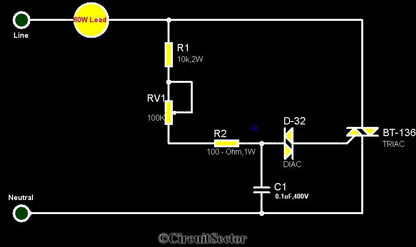
The triac-diac electronic fan regulator circuit is an efficient solution for controlling the speed of electric fans while minimizing energy consumption. The circuit utilizes a triac, a type of semiconductor device that can conduct current in both directions when triggered. The control of the triac is achieved through a diac oscillator, which serves as a triggering device. The D-32 diac is a key component that allows the circuit to switch on at a specific voltage level, providing a sharp transition that enhances the control of the triac.
The resistors R1 and R2 are used to set the biasing conditions for the diac, while the variable resistor RV1 allows for fine-tuning of the oscillator's time period. This adjustment directly affects the firing angle of the triac, which determines how much of the AC waveform is allowed to pass through to the fan motor. By controlling the amount of power delivered to the motor, the fan speed can be effectively regulated without the significant energy losses associated with traditional methods.
The capacitor (0.1uF 400V) in the circuit plays a crucial role in determining the oscillation frequency of the diac. Its value, in conjunction with the resistors, sets the timing characteristics of the oscillator, which in turn influences the firing angle of the triac. The overall design of the circuit emphasizes minimal heat generation and efficient power usage, making it suitable for applications where energy efficiency is a priority.
In summary, the triac-diac electronic fan regulator circuit provides a sophisticated method for adjusting fan speeds, leveraging the properties of triacs and diacs to achieve precise control while maintaining energy efficiency. The ability to adjust the firing angle through the diac oscillator allows for smooth and gradual changes in fan speed, enhancing user comfort and reducing electrical consumption.Circuit The circuit diagram provided is a triac - diac electronic fan regulator that would reduce your power usage of electric fans even in slow speeds. A normal resistor-inductor fan regulator heats up to waste eneegy when the fan is running with lowers speeds or it controls motor speed via applying resistance between fan and power supply.
This l ight dimmer/fan regulator circuit uses the principle of power control using a Tric. The triac turns On and Off varying the firing angle of the Triac. This can be done by a diac oscillator circuit. The diac oscillator consists of D-32 diac, R1, RV1, R2 resistors, a 0. 1uF 400V capacitor. The time period of this diac oscillator can be controlled by adjusting RV1. By doing this we can vary the firing angle of the triac thus the speed of the fan motor. 🔗 External reference
Related Circuits
The following circuit illustrates a simple light sensor circuit diagram. Features include crocodile technology for simulating circuit operation, and an LDR (Light Dependent Resistor) is utilized. The simple light sensor circuit operates on the principle of light intensity detection using...
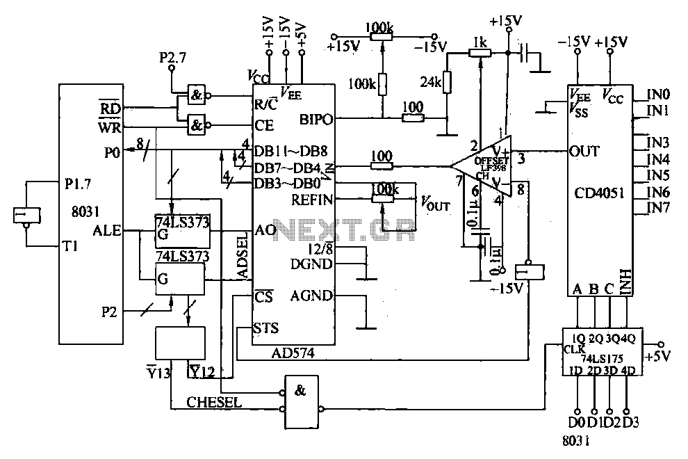
Converters and data sampling: A 12-bit A/D converter, AD574, is interfaced with an 8031 microcontroller circuit. Parameters are measured by a multi-way switch after a CD4051 strobe signal is sent to the sample/hold input device. The selection of the...
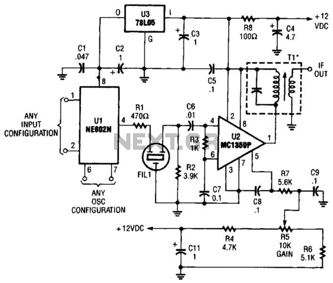
By using an NE602 with a filter and an MC1350P IC, a front end and an IF system for a basic superheterodyne receiver can be built with few parts. Tl is any suitable IF transformer for 262 kHz, 455...
A PoE Plus power level of 30 W can be achieved by utilizing an external MOSFET along with a controller that is compatible with the older standard. Power over Ethernet (PoE) technology enables the delivery of electrical power along with...
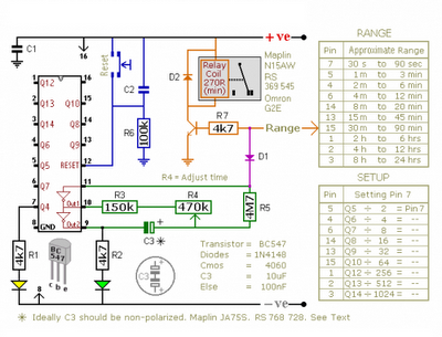
The CMOS 4060 is a 14-bit binary counter; however, only ten of these bits are connected to output pins. The 4060 also includes two inverters, which are connected in series across pins 11, 10, and 9. Together with resistors...
This design was created to address a challenge with the tailwheel doors of the P-51 Mustang. The issue arises from the complex undercarriage sequence, which would necessitate two independent sequencers. The closing sequence involves the main gear doors opening,...