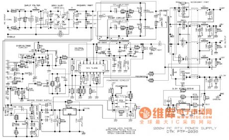
Switching Regulator Circuit
This example presents a switch DC regulated power supply circuit designed for buck-mode +5V applications. It consists of a power supply circuit, an impulsator, a voltage sampling or pulse width modulation circuit, and a buffering driver circuit, as illustrated in picture 5-38. The input conversion circuit includes a mains transformer (T), commutation diodes (VD1-VD4), a filter capacitor (C1), a current-limiting resistor, and a voltage regulator diode (VS). The impulsator features a time-base integrated circuit (IC), resistors (R1, R2), and capacitors (C2, C5). The voltage sampling or pulse width modulation circuit comprises capacitors (C3), resistors (R3-R5, R11-R13), and transistors (V4, V5). The switch DC regulated power supply circuit can deliver 3-15V DC voltage with a maximum current of 150mA, suitable for miniaturized electronic power supply applications. The circuit operates through a rectifying and wave-filtering stage, a switch control stage, and a voltage regulator stage, as shown in picture 5-37. The rectifying and wave-filtering bridge includes components such as commutation diodes (VD1, VD2) and filter capacitors (C1, C3). The switch control circuit consists of resistors (R2, R4), a voltage regulator diode (VS1), and a field effect transistor (VF). The voltage regulator circuit includes resistors (R1, R3, R5), a voltage regulator diode (VS2), a transistor (V), a diode (VD3), a filter capacitor (C2), and two three-terminal integrated regulators (IC1, IC2). It is critical not to draw voltage directly from C5 during operation to prevent short circuits that could damage V1 and V2. A short circuit can lead to a rapid increase in current through the coil (LO) of the flyback transformer (B1), resulting in excessive feedback that may cause component failure. This feedback is a series circuit feedback that can help open and protect the circuit, but increased load strengthens the feedback and decreases frequency, making the pliotron susceptible to damage. The switch DC regulated power supply circuit utilizes the TWH8778 electronic switching IC, providing high efficiency and a simple design for easy manufacturing. The output specifications are +12V and 1A. The circuit comprises an input conversion circuit, a switch output circuit, and an automatic voltage regulator circuit, as depicted in picture 5-39. The input conversion circuit includes a mains switch (S), a mains transformer (T), commutation diodes (VD1-VD4), and a filter capacitor (C1). The switch output circuit features an electronic switching integrated circuit (IC), resistors (R1, R2), a diode (VD5), an inductive coil (L), and capacitors (C2, C3). The circuit employs a voltage comparator (710), simplifying the design compared to previous versions. The divider regulator circuit consists of resistors (R1, R2, R3) and voltage diodes (VD1, VD2), which provide three distinct output voltages of 5V, 6V, and 18V from a 28V input. Additionally, resistors (R12, R13), a capacitor (C13), diodes (VD6, VD7), and a transistor (VT3) form the power soft-start circuit. Upon powering on, the drive pulse width of the VMOS tube (VT1) increases exponentially, and the comparator (710) initially cuts off the drive pulse to prevent excessive current flow in the energy storage inductor. When the switch (VT1) is turned off, the output voltage of the switching power supply continues to rise due to the current from the energy storage inductor.This example introduces the switch D. C. regulated power supply circuit of buck-mode +5V series. It is composed of power supply circuit, impulsator, voltage sampling or pulse width modulation circuit, buffering driver circuit and it is showed as the picture 5-38. The input converting circuit consists of mains transformer, T, commutation diode VD1-VD4, fi lter capacitor C1, current-limiting resistor and voltage regulator diode VS. The impulsator consists of time-base integrated circuit IC, resistor, R1, R2 and capacitor, C2, C5. The voltage sampling or pulse width modulation circuit is composed of capacitor, C3, resistor, R3-R5, R11-R13 and transistor V4 and V5. (View) The switch D. C. regulated power supply circuit introduced in the example can supply 3-15V D. C. voltage and its maximum current is 150mA, which meet the miniaturized electronics` power supply. Work`s Principle of the CircuitThe switch D. C. regulated power supply circuit is composed of rectifying and wave-filtering circuit, switch control circuit and voltage regulator circuit and it is showed as the picture 5-37.
The rectifying and wave-filtering bridge, UR, commutation diode, VD1, VD2 and filter capacitor, C1 and C3. The switch control circuit consists of resistor, R2 and R4, voltage regulator diode, VS1 and field effect transistor, VF.
The voltage regulator circuit is composed of resistor R1, R3, R5, voltage regulator diode VS2, transistor, V, diode, VD3, filter capacitor C2 and three-terminal integrated regulator IC1 and IC2. (View) When it isbeingused, it`s not proper to take voltage from C5 directly. It`s imposible to allow short circuit happened, otherwise it`ll burn V1 and V2. Because when short circuit takes place, the electric currentin coil LO of flyback transformer B1 will increase rappidly.
The voltage of coil L1 and L2 increases to a rather high level. It gives back the electric currentin V1 and V2 increasing as well. It causes intensive positive feedback. Finally it burns out as the limitation of power consumption of V1 and V2. This feedback of circuit belongs to series circuit feedback. And it can openand protectcircuit. But when load is increased, the feedback is strenghened. What`s more, the frequency will decrease as the load increases. The internal resistance is rather small, so short circuit will burn pliotron very easily. (View) The switch D. C. regulated power supply circuit introduced in the example uses TWH8778 electronic switching IC and it has high work`s efficiency, its circuit is simple which is easy to manufature. The output voltage and current of the power supply circuit are +12V and 1A respectively. Work`s Principle of the CircuitThe switch D. C. regulated power supply circuit is composed of input converting circuit, switch output circuit and automatical voltage regulator circuit and it is showed as the picture 5-39.
The input converting circuit consists of mains switch S, mains transformer T, commutation diode VD1-VD4 and filter capacitor C1. The switch output circuit is composed of electronic switching intergrated circuit, IC, resistor R1, R2, diode, VD5, induction coil, L and capacitor C2, C3.
(View) VMOS switching power supply circuit diagram. Because of adopting voltage comparator 710, so the circuit issimpler than former. As shown, resistor R1, R2, R3 and regulator VDl, VD2 form divider regulator circuit, three groups of 5V, 6V and 18V are separated from 28V input voltage, they areused as the power supply; resistors R12, R13, capacitor C13, diodes VD6, VD7 and transistor VT3 constitute the power soft-start circuit. The moment of power turn on, the drive pulse width of VMOS tube VTl increases exponentially. when the comparator 710 cut off the drive pulse firstly, it can prevent the current of energy storage inductor too large.
When the switch VTl cut down, the output voltage of switching power supply continues to rise because the current of energy storage inductor 🔗 External reference
