
Tracking FM Transmitter Schematics Schematic Diagram
The FM tracer circuit based on the LM3909 IC is designed to provide a simple yet effective solution for tracking signals in the FM band. The core of the circuit is the LM3909, which is a low-power IC designed for LED flashing applications, but its capabilities can be adapted for FM transmission. The circuit operates at a nominal voltage of 1.5V, making it suitable for use with small battery cells, which are commonly available and easy to use.
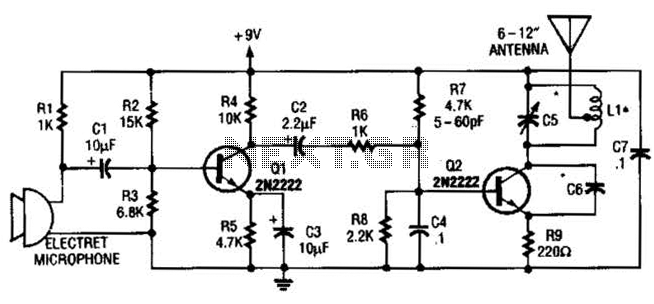
The circuit's design includes a few essential components: a power source (battery), the LM3909 IC, an LED for visual indication, a variable capacitor (C3) for tuning the frequency, and a standard 12-inch antenna for signal transmission. The consumption current of 3.7 mA ensures that the circuit can operate efficiently without draining the battery quickly.
To set the operating frequency, the user can connect the FM receiver to the output of the FM tracer. By adjusting the variable capacitor C3, the user can fine-tune the frequency until the receiver picks up the signal emitted by the FM tracker. The LED provides a visual confirmation that the circuit is functioning correctly, lighting up when the correct frequency is achieved.
The use of a standard antenna enhances the range and effectiveness of the FM tracker, allowing it to transmit signals over a reasonable distance. This project not only serves as an educational tool for those interested in electronics but also provides practical experience in circuit assembly, frequency tuning, and signal transmission. Overall, the 1.5V FM tracker represents a valuable learning opportunity in the field of electronics, combining theory with hands-on application.FM tracer was prepared using the LM3909 IC and some supporting components. 1. 5V FM trackers This will provide an indicator of revenue sources by providing a signal emitted by the LED. FM tracking uses a source voltage of the battery cell and fruit consumption current is 3. 7 mA. After completion of assembling Tracker FM 1. 5V, then the next step is setting the operating frequency of the FM tracker is, for convenience we can use the FM receiver and adjust the working frequency FM 1. 5V Tracking (tracking transmitter) by regulating C3. Have been obtained if the working frequencyTrackingFM 1. 5V (tracking transmitter) then the corresponding LED will light emitted by the transmitter information such as sound through an FM receiver is terdengan.
1. 5V FM tracker (tracking transmitter) can use a regular 12-inch antenna. Playing and learning electronics that will be happy, 🔗 External reference
Related Circuits
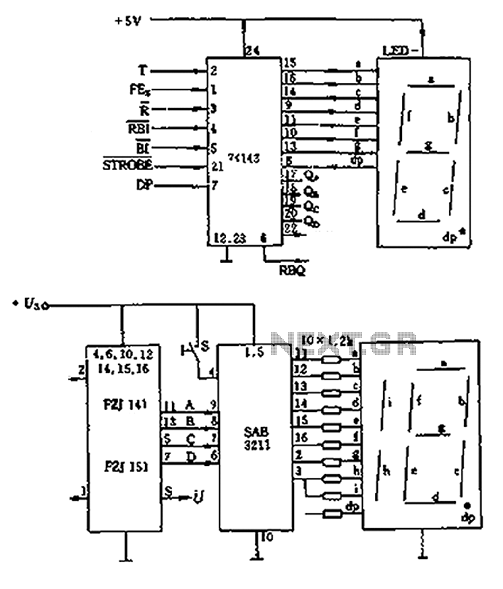
The decimal seven-segment storage decoding drive unit 74HC143 provides a constant output for all segments, each at a voltage of 5V and a current ranging from approximately 15mA to 22mA. The BCD data for the seven-segment decoder can be...
The UC3842AN is a pulse width modulation (PWM) integrated circuit that is commonly utilized in DVD, VCD, and SVCD players, as well as in computers, display systems, and various household appliances' switching power supply circuits. The UC3842AN is a...
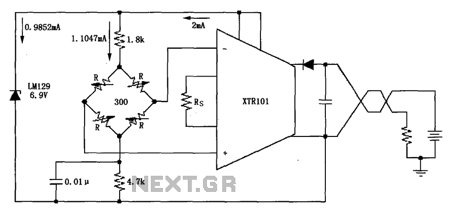
The circuit utilizes the LM129 voltage regulator to produce a 6.9V voltage reference, supplying a current of 1.0147mA from the 6.9V reference voltage to the bridge. The bridge may consist of varistor-type pressure sensors. The LM129 voltage regulator is a...
The vacuum tube remains relevant and functional in certain applications, such as in this continuous wave (CW) transmitter. The circuit is constructed in a traditional breadboard style on a wooden base. Old table radios serve as a valuable source...
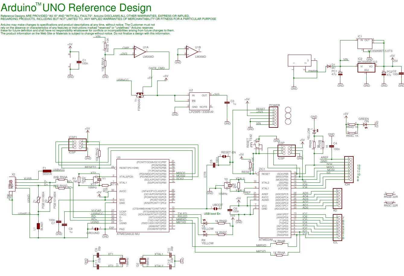
The Arduino Uno schematic diagram is available for viewing. The Arduino Uno is a microcontroller board that utilizes the ATmega328 chip. It features 14 digital input/output pins, of which 6 can function as PWM outputs, along with 6 analog...
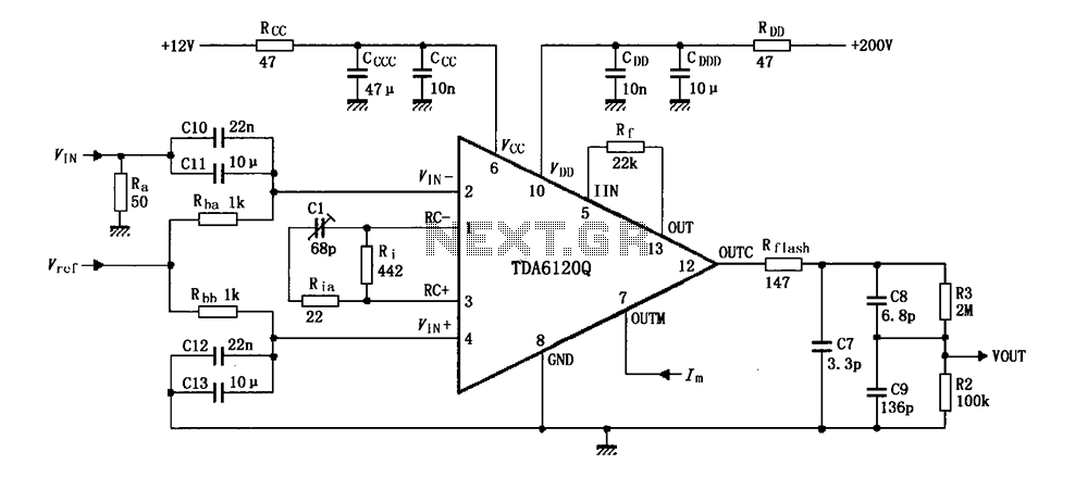
Feedback has indicated that the TDA6120Q test circuit, as shown in the figure, utilizes an input signal (Vi) composed of resistors Ra and capacitors C10 and C11, which are fed into the TDA6120Q at pins 2, 3, and 4....