
Triac Applications
The triac is a crucial component in various electronic control systems due to its ability to manage AC loads effectively. Its operation relies on the principle of gate triggering, where a small control signal at the gate terminal allows the device to conduct current in both directions. This bidirectional capability is particularly beneficial in applications requiring the control of AC power, as it simplifies the circuit design compared to using two SCRs in a back-to-back configuration.
In practical applications, the triac is often integrated into control circuits that require precise timing and control over the load. For example, in a motor speed control circuit, the triac can modulate the power supplied to the motor by adjusting the firing angle, thereby controlling the average voltage and current. This technique is commonly used in light dimmers and heating elements, where the power level needs to be varied.
The design of a triac-based control circuit typically includes protective components such as snubber circuits to manage voltage spikes and prevent damage to the triac. Additionally, heat sinks may be employed to dissipate heat generated during operation, ensuring the device operates within its specified limits.
When implementing a triac in a circuit, careful consideration must be given to the load characteristics and the required switching frequency. The limitations of dv/dt and the maximum current ratings must be adhered to in order to ensure reliable operation. Proper selection of components, including the gate resistor and snubber circuit, will enhance the performance and longevity of the triac in the application.
Overall, the versatility and efficiency of the triac make it an indispensable element in modern electronic control systems, capable of handling various loads and providing reliable performance in a wide range of applications.Next to SCR, the triac is the most widely used member of the thyristor family. In fact, in many of control applications, it has replaced SCR by virtue of its bidirectional conductivity. Motor speed regulation, temperature control, illumination control, liquid level control, phase control circuits, power switches etc.
are some of its main applicati ons. However, the triac is less versatile than the SCR when turn-off is considered. Becausethe triac can conduct in either direction, forced commutation by reverse-biasing cannot beemployed. So turn-off is either by current starvation, which is usually impracticable, orelse by ac line commutation.
There are two limitations enforced on the use of triac at present state of commercially available devices (200 A and 1, 000 PRV). The first is the frequency handling capability produced by the limiting dv/dt at which the triac remains blocking when no gate signal is applied.
This dv/dt value is about 20 Vmicros-1 compared with a general figure of 200 Vmicro s-1 for the SCR, so that the limitation of frequency is at the power level of 50 Hz. The same dv/dt limitation means the load to be controlled is preferably a resistive one. When high frequencies and high dv/dt are involved then the back-to-back SCRs cannot be replaced by the triac.
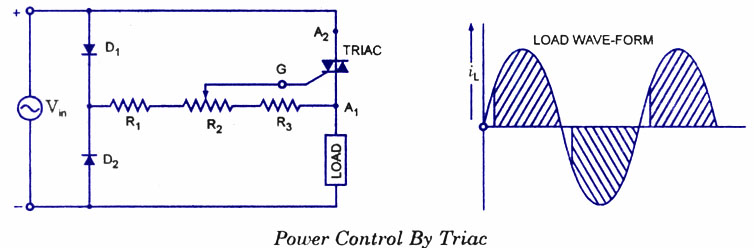
Use of the triac as an ac on/off switch is shown in figure. When the switch S is in position 1, the triac is cut-off and so the lamp-is`dark. When the switch is put in position 2, a small gate current flowing through the gate turns the triac on and so the lamp is switched on to give rated output. A triac control circuit is shown in figure. Here it is controlling ac power to load by switching on and off during the positive and negative half cycles of the input sinusoidal signal.
During the positive half cycle of the input voltage, diode D1 is forward biased, D2 is reverse-biased, and the gate terminal is positive with respect to A1 During the negative half cycle, the diode D2 is forward biased and diode D1 is reverse-biased, so that the gate becomes positive with respect to terminal A2- The point of commencement of conduction is controlled by adjusting the resistance R2. 🔗 External reference
Related Circuits
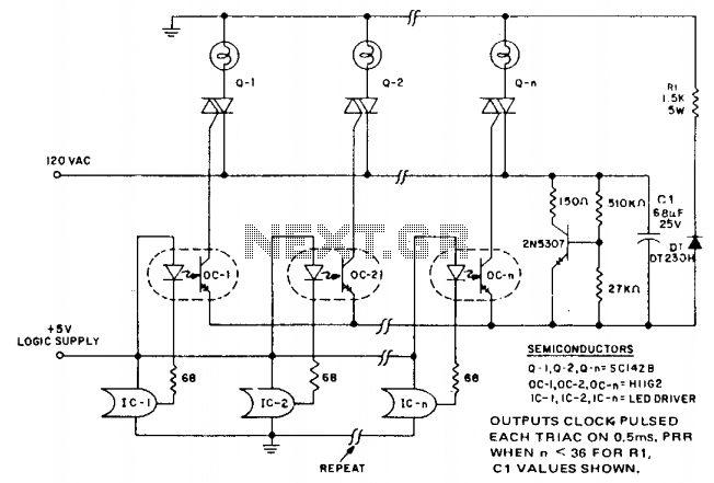
In microprocessor control of multiple loads, minimizing the cost per load is essential. A typical application is a large display that drives arrays of incandescent lamps. This circuit achieves minimal component cost per stage by utilizing optocoupler triggering of...
Light Sensitive Staircase Switch with Triac. The operation of the third circuit is quite similar, except that it incorporates photo sensitivity. The circuit is illustrated in the schematic. When there is insufficient light... The light-sensitive staircase switch circuit utilizes a...
This solid-state relay circuit operates using 120 volts from household mains and should only be constructed by individuals with the necessary knowledge and skills to ensure safety. Failure to do so may result in personal injury or property damage. The...
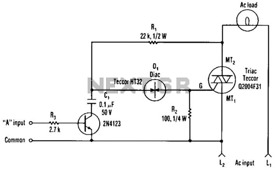
The single transistor connected between the capacitor and the common side of the AC line allows a logic-level signal to control this TRIAC power circuit. Resistor R2 prevents false triggering of the TRIAC by the trickle current through the...
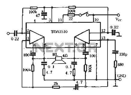
TDA1510 is an audio power amplifier from Philips. This integrated circuit (IC) includes features such as load short protection, open load detection, and an overheat protection circuit. It offers stable output voltage, excellent ripple rejection performance, requires fewer external...

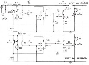
A closed light switch S allows 220V AC to flow through resistors RP1 and RP2, charging capacitor C2. When the voltage across C2 reaches the breakover voltage of the diac VD, the diac and triac activate sequentially, energizing the...