
Variable Frequency Oscillator Circuit with Schematic

The NE555 timer IC is a versatile and widely used device in various electronic applications, particularly in generating precise timing and oscillation signals. In the context of a variable low-frequency oscillator, the NE555 can be configured in astable mode, where it continuously switches between its high and low states, producing a square wave output.
To design the oscillator, the key components include the NE555 timer, resistors, and capacitors. The frequency of oscillation is primarily determined by the values of two resistors (R1 and R2) and a capacitor (C1) connected to the NE555. The relationship between these components can be expressed through the formula:
\[ f = \frac{1.44}{(R1 + 2R2) \times C1} \]
Where:
- \( f \) is the frequency of oscillation,
- \( R1 \) is the resistor connected between the discharge pin and Vcc,
- \( R2 \) is the resistor connected between the discharge pin and the threshold pin,
- \( C1 \) is the timing capacitor connected between the threshold pin and ground.
By varying the values of R1, R2, and C1, the output frequency can be adjusted, allowing for a range of low-frequency signals to be generated. The output from the NE555 can be taken from the output pin (pin 3), which provides a square wave signal suitable for driving other circuits or components.
The schematic typically includes the NE555 IC, power supply connections, and the arrangement of resistors and capacitors that define the oscillation frequency. Proper decoupling capacitors may also be included to ensure stable operation of the IC. Additionally, it is important to consider the power supply voltage, as the NE555 can operate within a specified range, typically from 4.5V to 15V, depending on the specific variant of the IC used.
This configuration can be employed in various applications such as tone generation, pulse-width modulation, and timer circuits, showcasing the flexibility and utility of the NE555 in electronic design.A NE555 IC is used for designing the variable low frequency oscillator and schematic is also given.. 🔗 External reference
Related Circuits
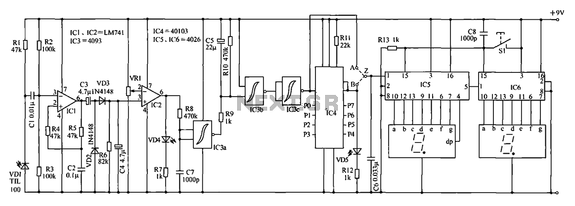
The digital counter circuit described utilizes an infrared signal to detect moving targets, making it suitable for counting small devices on a production line as they move along a conveyor belt. This circuit can also be employed for various...
This schematic represents a version of a simple LED chaser. A 555 timer is not utilized due to its high cost at local electronics stores, which is over $4 CAD. Instead, an oscillator is constructed using two sections of...
This project utilizes an LM338 adjustable three-terminal regulator to deliver a current of up to 5A with a variable output voltage ranging from 2V to 25V DC. It is particularly useful for powering various electronic circuits during the assembly...
Analyzing the three-phase winding involves examining the head and tail of various therapies, such as the use of hair bundles. The process is simple, safe, and quick. The analysis includes crimping electrical connections, as shown in FIG. 1. The...
The Light Switch with Relay is a series of electronic switches that are controlled by light intensity. This circuit can automatically control lighting, turning the lights on when ambient light levels decrease. The threshold for light activation in the...
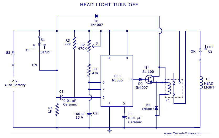
A circuit that can automatically turn off the headlights or lamps of a vehicle after a preset time. This light switching circuit is constructed using a 555 timer integrated circuit (IC). The described circuit utilizes the 555 timer IC in...