
h bridge driver circuit

The regenerative effect observed in a 4-quadrant inverter highlights the importance of effective power management in both industrial and low-power applications. In the context of an H-bridge configuration, the inverter's ability to handle regenerative braking is crucial. For low-power systems, such as those operating within the 1W-5W range, the design must ensure that switching times are optimized to prevent shoot-through conditions, which can lead to catastrophic failures.
In this H-bridge design, the choice of a 12V operating voltage is significant. The implementation of pull-up resistors simplifies the control of the upper FETs but requires careful consideration of gate driving techniques. Isolated gate drivers are essential for the upper FETs to ensure that gate-source voltages are adequately managed, especially as the voltage increases. The transition speed of the FETs is a critical parameter; thus, a gate resistor value of around 100 ohms is recommended to enhance switching performance, while also consulting the respective datasheets for the FETs used.
In the application of a CNC router/plotter, the requirement for multiple PWM signals necessitates a robust control strategy. The proposed method of utilizing an inverter IC to generate complementary PWM signals is valid, but careful attention must be paid to the inverter's switching speed to avoid delays that could compromise performance.
Furthermore, the discussion on the use of inductors in series with the FETs raises important considerations regarding design philosophy. While inductors can mitigate shoot-through by limiting the rate of change of drain current, their inclusion in a voltage-source inverter design contradicts the goal of minimizing inductance to maintain a pure voltage source. The placement of high-pass filter capacitors at the gates of the FETs must also be scrutinized, as insufficient gate current may hinder effective switching, thereby impacting overall circuit performance.
Finally, strict adherence to control logic is imperative to prevent simultaneous activation of upper and lower switches in the same leg, which could create a direct current path and result in shoot-through conditions. Properly managing these elements will ensure the reliability and efficiency of the inverter circuit in practical applications.The so-called regenerative effect of a 4-quadrant inverter. Yup you will need to dissipate that power somewhere. In big industrial drives this gets re-inverted onto the national grib, but hear I would suggest a braking cct. For low-power stuff (1W-5W) they are ok, but for more power, the mis-match in switching times starts to become a major hindra
nce in ensuring no switching shoot-throughs. My only concern with this design is to do with your operating voltage. This H-bridge has been setup to run at 12V, as a result they can use the cheaky pull-up resistors to turn on/off the upper FET`s You are going to have to have an isolated Gate-drive for (at least) the upper two FET`s, giving them a floatingh supply to allow the gate-source to be switched local to this isolated supply. Whith working at a higher voltage the speed at which you turn the FET`s on is going to become more important.
The problem with this 12V design is it uses a 10k to turn OFF/ON which is bloody slow. You are going to want to turn these FET`s on alot faster so a gate resistor in the order of 100R is needed (but check datasheets) Hmmm. guess this is going to be more difficult than I thought. The motors are rated for 42 volts, but I dont have to run them at that voltage, I think I`ll just give 12V a try and see if it is sufficient.
As long as it can handle the current (roughly 5-6 amps when stalled at 12V) I should be ok. Hmmm. guess this is going to be more difficult than I thought. The motors are rated for 42 volts, but I dont have to run them at that voltage, I think I`ll just give 12V a try and see if it is sufficient. As long as it can handle the current (roughly 5-6 amps when stalled at 12V) I should be ok. I`m trying to make a simple CNC router/plotter. The motor is originally off of a 1 dimensional plotter (the pens would move back and forth on a slide and the paper would be fed by another motor).
but it looks like it requires 4 PWM signals. Can I just feed the PWM signal into A and an inverter IC, then take the inverted PWM signal and put it on Input C I dont really see a problem with this as long as I`m using a high speed inverter, but I`m probably wrong. 2) Place inductors in series with the FETS. I`ve seen this done is power applications that limit the shoot through based on limiting the rate of change of drain current.
You sure about this The whole purpose of a voltage-source inverter is to reduce the inductance to the H-bridge to provide a pure voltage-source to the load. The addition of extra inductance in anything BUT the load (or before the DC-link capacitor when supplied from a rectifier) is counter-intuitive to a voltage-source inverter W.
r. t. the topology posted, I am a bit confused to why the high-pass filter caps are at the gate of the FET`s Are you doing this to provide capacitve isolation to allow the switching of the FET`s such a scheme will not provide anywhere near enough gate-current to allow the FET`s to switch at a decent (let alone recomended ) speed 2) Place inductors in series with the FETS. I`ve seen this done is power applications that limit the shoot through based on limiting the rate of change of drain current.
1) Commanded. You have no purpose EVER to turn an UPPER and a LOWER Switch in the same LEG on EVER!, but if there is a problem in your control (something you overlooked) you could turn both on. This situation is very bad 2) switching: In a phase LEG the UPPER and LOWER switches are fed the compliment PWM signal (so they are never commanded ON at the same time).
However, switches do not turn-on/off instantaniously, it take time IF you command the upper to turn-off and the lower to turn-on at the same time (or vica verca) then there will be instances where you have provided a path for current to flow through a leg BAD! the current flowing will not be as bad as if it was a commanded shoot-through (since the devices are transitioning between states) but the k
🔗 External reference
Related Circuits
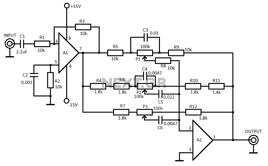
This 3-band equalizer circuit is an active filter network designed to adjust bass, midrange, and treble audio frequencies. It utilizes the LM833 operational amplifier from National Semiconductors, which is known for its very low noise figure and wide frequency...
The current feedback operational amplifier maintains a consistent bandwidth even when the open-loop gain is altered. This characteristic makes it particularly suitable for applications in video signal amplification and the driving circuits of video cables. The accompanying diagram illustrates...
It was observed that balls were becoming lodged in the ball trough, failing to load into an upkicker or not resting correctly on the trough ball microswitches or optos, which caused the machine to register a missing ball. Initially,...
This UHF transmitter is designed for low power applications such as remote controls for garage doors, operating systems, and wireless alarms. This UHF FM transmitter is equipped with... This UHF transmitter operates within the Ultra High Frequency (UHF) band, which...
This circuit consists of a 6 Zone Alarm system with an LED display. The alarm system features 6 independent zones and includes a 7-segment LED display, along with one timed entry/exit zone. The 6 Zone Alarm system is designed to...

This is a design circuit for a UHF transmitter. The TV transmitter operates within the UHF frequency range of 470-580 MHz, specifically on channels 21-34. It can transmit signals over distances of 30-100 meters using a cable length of...