
Feedback resistance circuit diagram of current feedback operational amplifier
The current feedback operational amplifier (CFOA) is designed to provide high-speed performance while preserving bandwidth, making it suitable for various applications, especially in video processing systems. Unlike traditional voltage feedback operational amplifiers, which exhibit a trade-off between gain and bandwidth, CFOAs maintain a constant bandwidth over a range of gain settings. This unique property is essential for video signal amplification, where signal integrity and fidelity are critical.
In video applications, the CFOA can efficiently amplify the in-phase components of the video signal, ensuring that the output remains synchronized with the input. The use of the AD844 operational amplifier is particularly advantageous due to its high bandwidth and fast slew rate, which are essential for handling the rapid changes in video signals without introducing distortion or delays.
The schematic for the video in-phase amplification circuit typically includes the CFOA configured in a non-inverting configuration, allowing for a gain that can be easily adjusted by changing the feedback resistor values. Additional components such as capacitors may be included to filter out unwanted high-frequency noise, ensuring that only the desired frequency components of the video signal are amplified.
The design considerations for implementing the AD844 in this application involve careful selection of resistor and capacitor values to optimize the gain-bandwidth product and minimize signal degradation. It is also crucial to ensure proper power supply decoupling to maintain stability and performance, particularly in high-frequency applications.
Overall, the current feedback operational amplifier, exemplified by the AD844, plays a vital role in modern video signal processing, enabling high-quality amplification while preserving signal integrity across varying gain settings.About the current feedback operational amplifier, even if the open-loop gain was changed, the bandwidth also will not be changed. It is often used in video signal amplificaion and the drive circuit of video cable. The diagram is a vedio inphase amplification circuit. If the broadband high-speed voltage feedback op amp AD844 is adopted, it need to have.. 🔗 External reference
Related Circuits
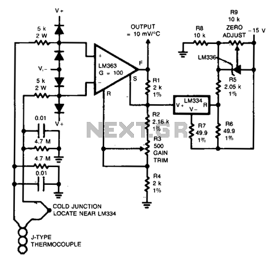
Input protection circuitry allows the thermocouple to short to 120 Vac without damaging the amplifier. Calibration: Apply a 50 mV signal in place of the thermocouple. Trim R3 for V0UT = 12.25 V. Reconnect the thermocouple. More: Trim R9...
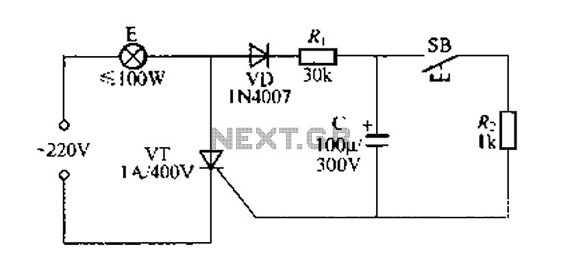
Figure 57 illustrates a simple delay lamp circuit that connects to lamp E using a two-wire connection. This design allows for the security bars to be installed directly, enabling replacement with a standard wall switch without altering the existing...
This document outlines a simple SWR (Standing Wave Ratio) protection circuit that can be easily constructed. The directional coupler and detector components are sourced from an old VHF SWR meter. It is advisable to replace the existing RF bypass...
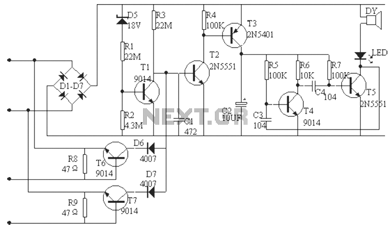
The phone alarm device is designed to monitor and prevent unauthorized use of a telephone line. When interference signals are detected on the line due to theft attempts, the alarm activates, preventing the thief from making calls while alerting...
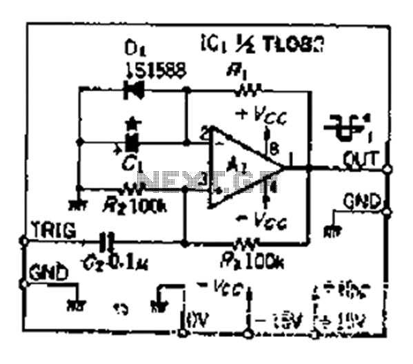
Although people believe that using a timer with an operational amplifier (op-amp) does not yield significant results, it can still be advantageous in certain scenarios. In environments with high noise levels, the application retains its benefits. When the phase...
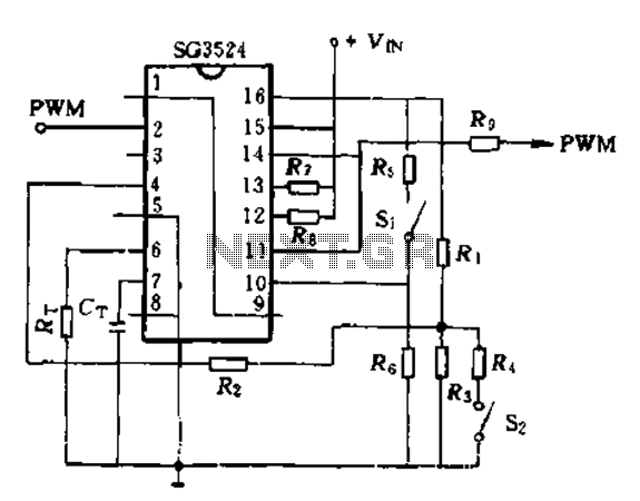
The SG3524 is utilized solely as a pulse width modulator. The error amplifier is configured in a follower arrangement. As illustrated in Figure 10-7, the ACR output connects to PWM output pin 2, which serves as the control signal....