

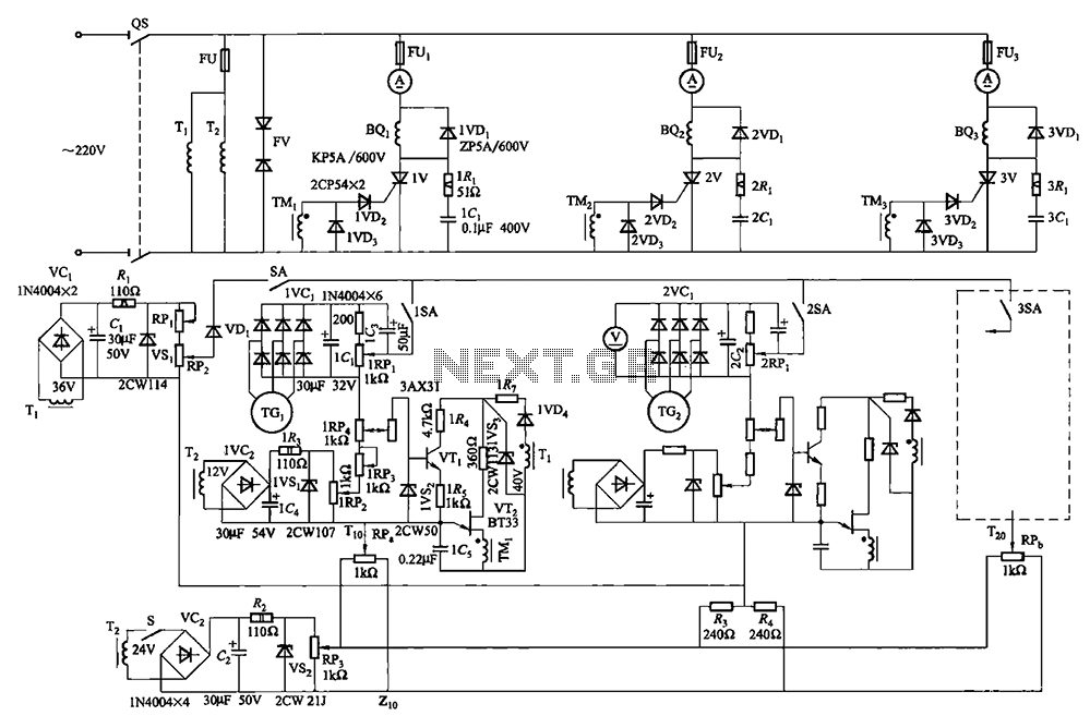

Multi-unit slip motor speed control system synchronous operation circuit
Collaboration with the dancers balanced bridge long on the porcelain unit Sync adjustment rheostat speed control system shown in Figure 3 to 183 in FIG. Others...
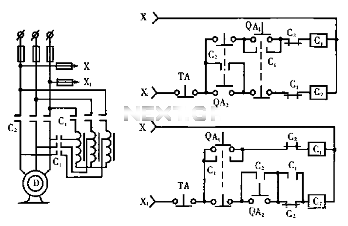
High-power motor control circuit summary
Circuit works (only the relevant parts of the manual draw mode): Figure a shows a circuit schematic circuit; Fig. B Typical electricity as conventional seconda...
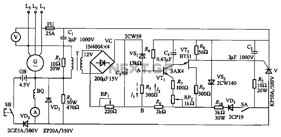
KL-25 type automatic thyristor excitation device circuit
Circuit shown in Figure 7-32. The excitation device is suitable for terminal voltage of 400V, a capacity of less than 75kW synchronous generator motor for auto...
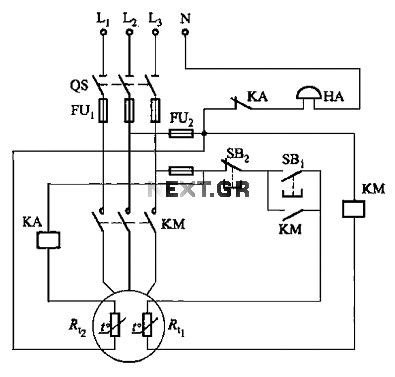
PTC phase asynchronous motor circuit protection one
Circuit shown in Figure 4-2. It uses two thermal resistors, a (Rc,) is used as overload protection, another (Rt :) used as an alarm. ...
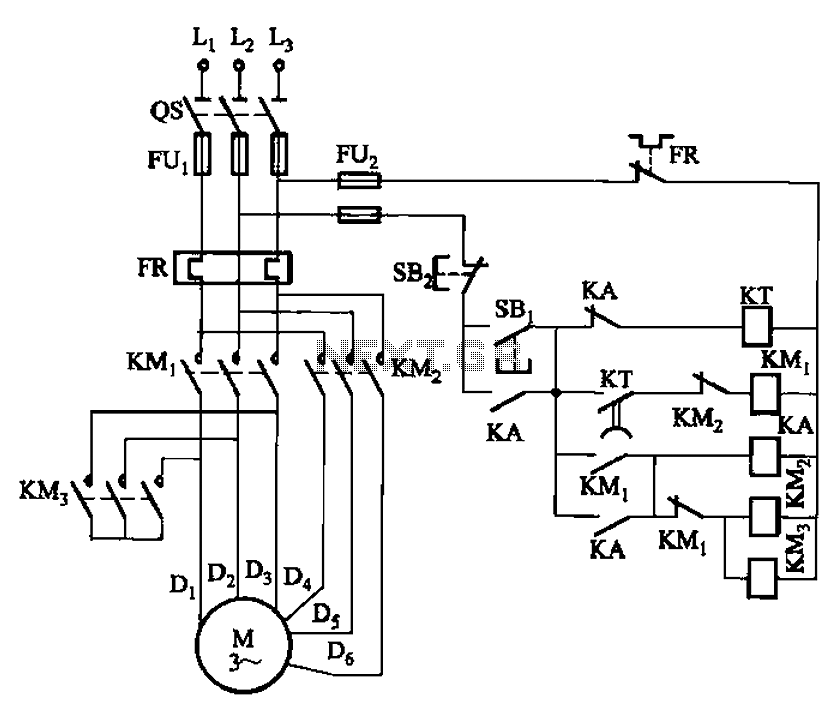
2Y- connection two-speed motor contactor control circuit of the four
Circuit shown in Figure 3-99. The low start-up circuit to the motor ( shaped connection), then automatically accelerated speed into high speed (2Y-connector) o...
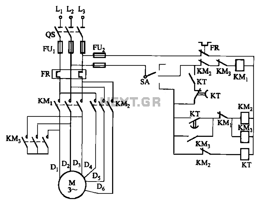
2Y- connection three two-speed motor contactor control circuits
Circuit shown in Figure 3-98. Motor starting and low-speed operation is controlled by a switch SA. Adjust the time relay KT, the motor can be changed from low ...
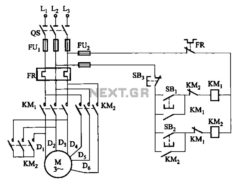
2Y- connection two-speed motor contactor control circuit 2
Circuit shown in Figure 3-97. The circuit only two contacts, the circuit is simple, but only applies to the following 2kW dual speed motor. Figure, SBi is runn...
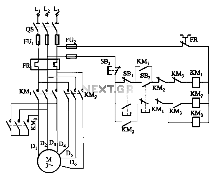
2Y- connection two-speed motor contactor control one circuit
Circuit shown in Figure 3-96. Figure, SBz is running at low speed button, SBi as the high-speed operation button. SB3 for the stop button. In this circuit, a m...
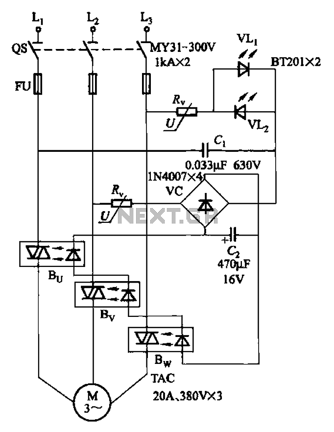
Three-way operation allows the motor-controlled circuits
Circuit shown in Figure 3-93. It is coupled with optical phase sequence protection relay. ...
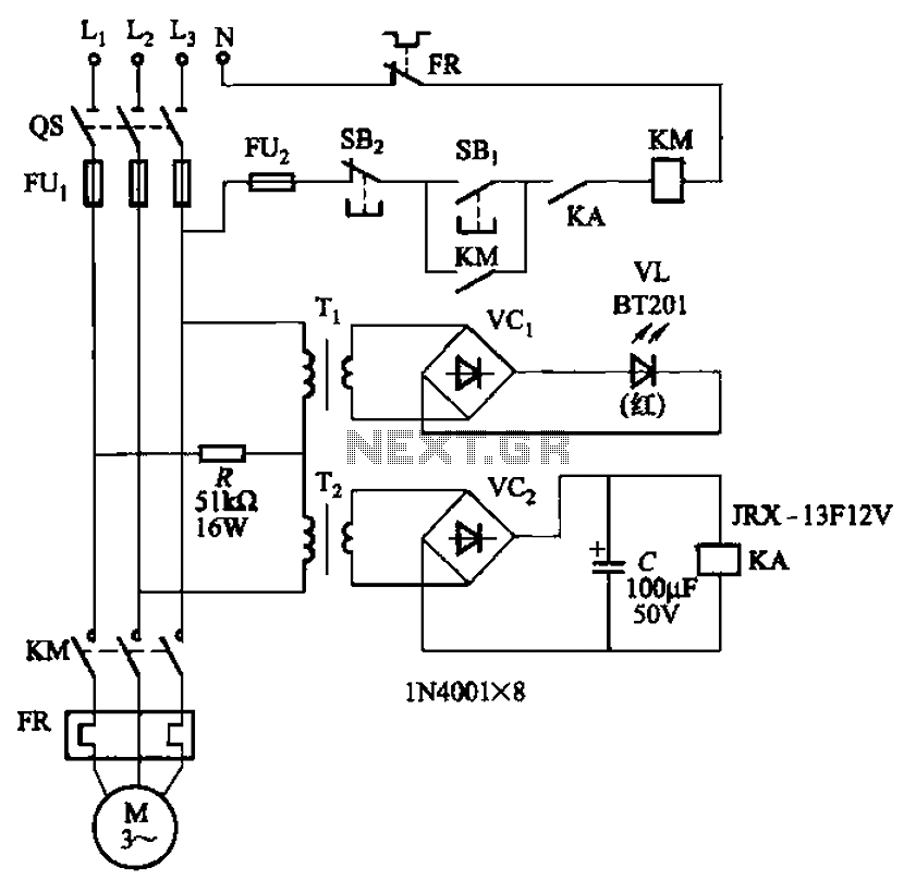
Allowing only one-way operation of the motor-controlled circuit 2
Circuit shown in Figure 3-92. It uses dual-phase sequence protection relay sense. When the power positive phase sequence (U, V, w), following the electrical KA...
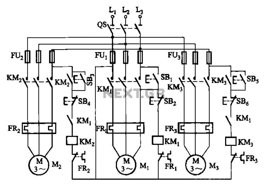
Three motor control circuit start and stop sequence requirements
Circuit shown in Figure 3-89. After starting the motor Mi can guarantee, it allowed the other two to start the motor. Shutdown, power motivation Mz, can first ...
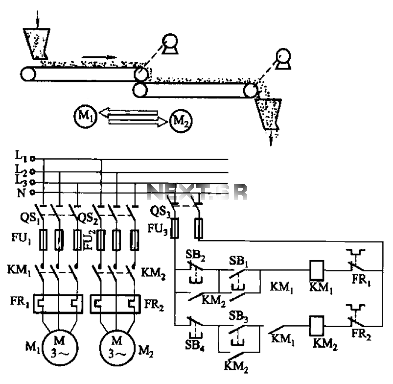
Belt conveyor interlock motor operation sequence control circuit
Circuit shown in Figure 3-86. The line utilization time relay to control two motors, one of the first than the other after starting stall. Adjust the time rela...
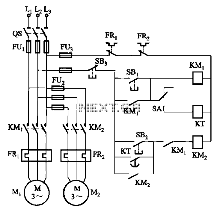
Two electric motors has started manual and automatic control circuit
Circuit shown in Figure 3-85. Manual and automatic control through the transfer switch SA. After starting the motor Mi, to start. Automatic start sequence by t...
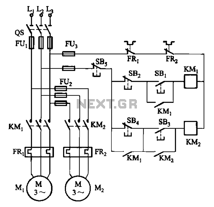
Host stall after stall to auxiliary control circuit
Circuit shown in Figure 3-84. Be seen by the two electric motors can be started separately. But only when you press Host (Ml) of the stop button SBz (after con...
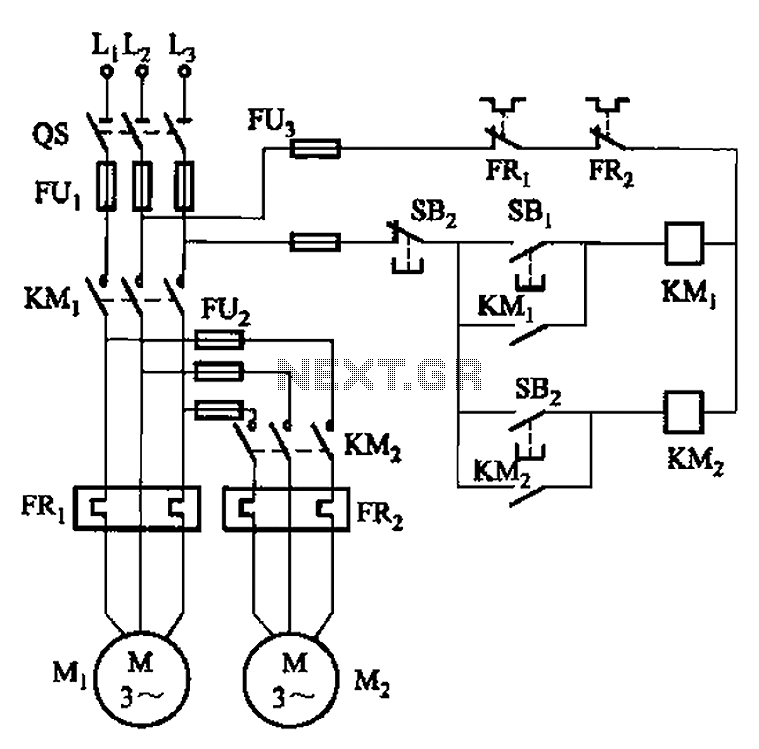
The main circuit in order to start the control circuit
Circuit shown in Figure 3-83. The figure shows that only when the contactor KMi after pull (ie, after the motor Mi first start), KM2 to pull (ie Mz after start...
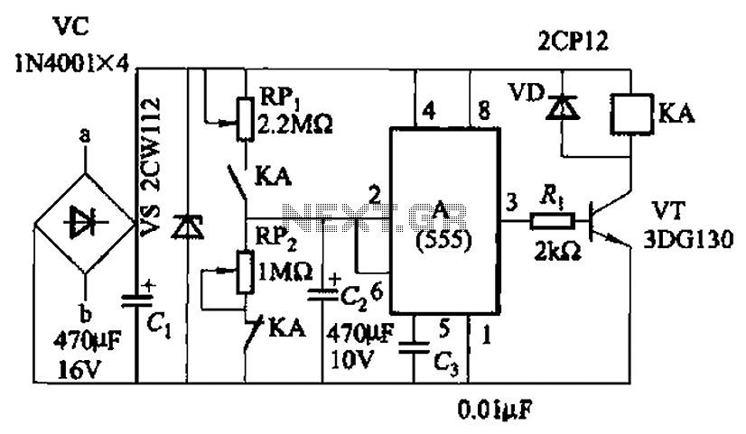
Intermittent start-stop cycle control circuit of seven b
Circuit shown in Figure 3-82. It uses 555 IC A motor to achieve automatic control of start and stop cycles. Adjust potentiometer RPi and RPz, respectively, to ...
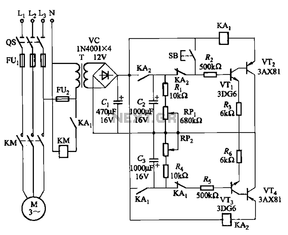
Intermittent start and stop cycle control circuit of the four
Circuit shown in Figure 3-79. It consists of two delay circuits, respectively. RPi adjustment potentiometer and RP2, respectively, can be changed and stop the ...
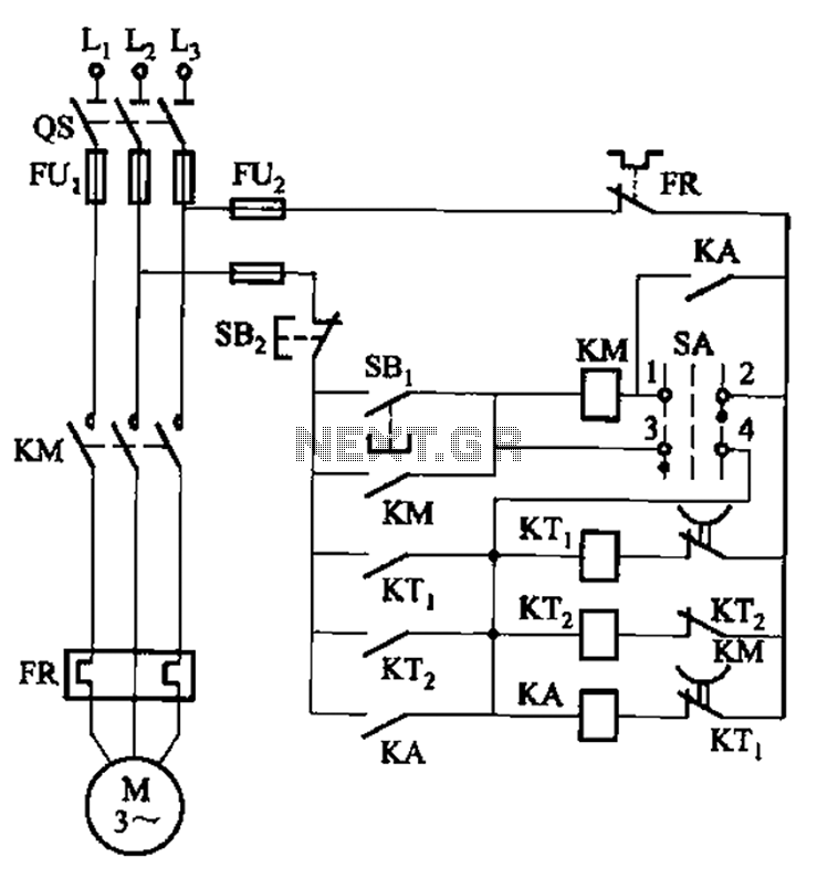
Third batch start and stop cycle control circuits
Circuit shown in Figure 3-78. The time line also use two relays to achieve automatic control, but the line structure than simple. The line can be achieved inte...
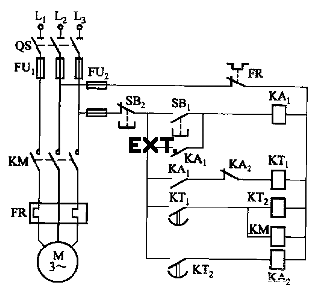
Intermittent one start and stop cycle control circuit
Circuit shown in Figure 3-76. It uses two time relay to achieve control. KTi and KTz control the motor running and downtime. ...
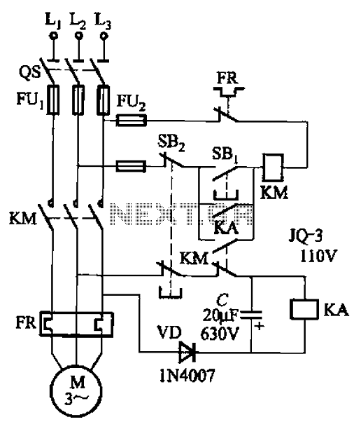
The use of self-induced emf achieve instant protection circuits
Circuit shown in Figure 3-73. The line is to use the power of instantaneous power failure, the self-induced emf generated by the motor to implement now instant...