
sound Circuits
The described circuit utilizes a breadboard layout that facilitates prototyping and experimentation with electronic components. The conductive strips serve as a means of distributing power and ground throughout the circuit, allowing for easy connections to various components. The two long strips along the sides are dedicated to power (+) and ground (-), providing a stable reference voltage for the circuit. The perpendicular rows in the center of the breadboard enable the placement of various electronic components, such as resistors, capacitors, and integrated circuits.
The mention of a potentiometer (or fader) with a resistance range of 0 to 10K or 20K ohms indicates its role in controlling the amplitude of a signal, which is crucial in audio applications. However, caution is advised when setting the potentiometer to its minimum resistance, as this condition creates a short circuit, potentially damaging the LED and other components. The burning plastic smell serves as an indicator of overheating, emphasizing the need for careful handling during experimentation.
The oscillator connection suggests that the circuit may involve signal generation, which is often critical in electronic music applications. Proper orientation of the IC, particularly with the semicircular indentation, ensures correct functionality, as ICs have specific pin configurations that must be adhered to. The unmarked wires indicate that they are used for interconnections, which are essential for establishing the necessary pathways for current flow within the circuit.
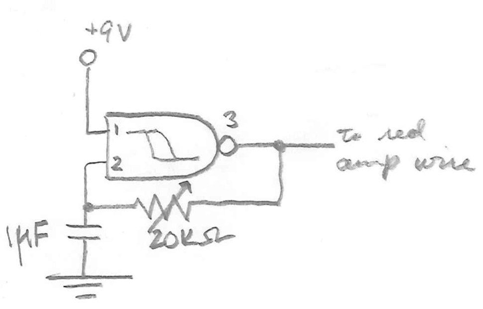
The circuit diagram's representation of a NAND Schmitt trigger highlights the logic function of the IC, which is fundamental in digital electronics. This type of circuit is known for its ability to provide clean transitions between high and low states, making it suitable for applications requiring precise timing and signal conditioning. The reference to the datasheet and additional literature on hardware hacking provides valuable resources for understanding the specifications and operational characteristics of the components used in the circuit, enabling further exploration and experimentation in electronic design.This is a slightly less professional-looking version of Handmade Electronic Music, with almost identical content (and free!). See in particular Chapters 18 and 20. Layout of conductive metal strips under the breadboard performations. There are generally two long strips running down each side for power (+) and ground (-) and many rows of perpendicu
lar strips down the middle. Fader hook-up. NOTE: the pot`s resitance varies between 0 and 10K or 20K ohms. If it`s turned down all the way, the circuit will short because there`s no resistance, and the LED will give off a funny burning-plastic smell and stop working (as we discovered in class!). Oscillator hook-up. Orient the IC with reference to the its semicircular intent. Unmarked components are wires. Note the wires at the bottom of the board running power (+) and ground (-) to the long strips on the other side.
Circuit diagram, representing the logic inside the IC (a NAND Schmitt trigger) rather than the IC itself. See the datasheet and "Hardware Hacking" page 75 for more info. The IC ground and power are implied, as is the amp ground. 🔗 External reference
Related Circuits

The piezo transducer functions as both a sound pickup device and a frequency-selective filter. By adjusting the gain of the operational amplifiers (op-amps), the oscillator can be configured as a sensitive and frequency-selective tone decoder circuit. When the gain...

A computerized infrared remote project is a simple device designed for recording and playing back streams of infrared data, specifically the codes transmitted by remote controls. Software is provided for use in both DOS and Windows environments, along with...

The USB sound card circuit utilizes the PCM2702 integrated circuit (IC) to create a fully functional USB sound card. The design is straightforward, allowing for the easy implementation of audio processing capabilities. The PCM2702 is a versatile USB audio controller...

This circuit generates the sound of two canaries singing in a cage. Two LM324 quad amplifiers constitute seven oscillators. One oscillator serves as an on/off control, while the remaining six produce the sounds of two canaries. A 9-V supply...

AM radio receivers demodulate amplitude-modulated (AM) signals. The primary source of these signals is the Standard AM Radio Broadcast Band, although shortwave stations also utilize AM modulation. Amplitude modulation was developed between 1900 and 1917 by amateur radio enthusiasts....

This is a car alarm simulator that uses an LED as a simulation output. This simple circuit can indicate whether a car is running or not by detecting the voltage difference when the car is on or off. This...