
temperature sensor circuit
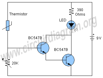
The temperature sensor circuit utilizes a thermistor, which is a critical component that responds to temperature changes by altering its resistance. This property allows it to function effectively in detecting thermal variations. The BC547B transistors, arranged in a Darlington configuration, provide a significant amplification of the current, thereby increasing the circuit's sensitivity to small changes in temperature. The Darlington pair is particularly advantageous in applications where a higher gain is required, enabling the circuit to respond to subtle temperature shifts.
The LED serves as a visual indicator, illuminating when the circuit detects a sufficient increase in temperature. The current-limiting resistor is essential to prevent excess current from damaging the LED, ensuring longevity and reliable operation. The inclusion of a 20K variable resistor allows for fine-tuning of the circuit's response, enabling the user to set the desired activation temperature for the LED.
In summary, this simple temperature sensor circuit is an effective solution for heat detection, leveraging the properties of a thermistor and the amplification capabilities of a Darlington pair to provide a reliable output in the form of an illuminated LED. The design is user-friendly and can be easily assembled with minimal components, making it suitable for various applications in temperature monitoring and alarm systems.The schematic shown here is a project of a simple temperature sensor circuit or we can also say it a heat sensor circuit, which will activate an LED when receive heat. The circuit is easy to make and using only few components. The two BC547B transistors are connected as a darlington pair to increase the sensitivity of the circuit.
Other components of the circuit are an LED, a current limiting resistor for LED, a 20K variable resistor and a thermistor. A thermistor is a device that limits the passing of current through it according to the temperature. In the condition of low temperature they have higher resistance and in the opposite condition when they receive heat their resistance starts decreasing rapidly and current starts to flow.
Working of the circuit is simple when the thermistor will receive heat its resistance will decrease due to which the transistors will become switched on and the voltage will starts passing through the transistors which will activate the LED. The 20K resistor is used to adjust the circuit to activate the LED on the required heat or temperature.
🔗 External reference
Related Circuits

The ZXLD1100 is a PFM flyback DC to DC boost converter that operates in discontinuous mode. The following circuit diagram illustrates the configuration of four LED drivers for handset LCD backlighting using this device. The ZXLD1100 is designed to...

The circuit diagram includes an input filter capacitor C1 and a primary clamp composed of VDz and VD1. The resistor R1 is connected to the control terminal. C2 serves as a bypass capacitor. The TOP414GC-S is connected in parallel...

In this fire alarm circuit project, a thermistor functions as the heat sensor. When the temperature rises, its resistance decreases, and conversely, when the temperature falls, its resistance increases. Under normal conditions... In this fire alarm circuit, the thermistor is...

The UTC H654 is an integrated Hall sensor with complementary output drivers designed for the electronic commutation of brushless DC fans. It consists of an on-chip Hall voltage generator, a differential amplifier Schmitt trigger, and an open-collector output all...

In pulse position modulation, the amplitude and width of the pulses are kept constant, while the position of each pulse with reference to the position of the reference pulse is changed according to the instantaneous sampled value of the...

The saving lamp circuit features two main types: glass cover and exposed. The glass cover variants include three series: spherical, cylindrical, and processing types. The first two series consist of four variations: transparent, carved, engraved, and white. These lamps...