


positive negative probe with ic 555
#IC 555
#voltage probe
#LED indicator
#automotive
#positive-negative detection
#5-15V
#simple circuit
#DIY electronics
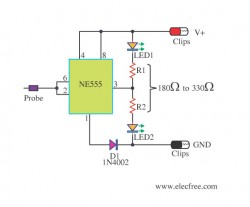
Description: This circuit allows users to determine whether a specific point in the circuit is at a positive or negative voltage. It is an inexpensive circuit that utilizes minimal components, making it suitable for use in automobiles or motorcycles. The circuit operates within a voltage range of 5 to 15 volts. When the circuit is powered, two LEDs light up to indicate the voltage status. If a positive voltage is detected at pin 3 of the IC 555, the red LED illuminates while the green LED turns off. Conversely, if a negative voltage is detected, the red LED turns off and the green LED lights up. A 1N4002 diode is included to protect against reverse polarity. Further details can be found in the accompanying circuit diagram.
This circuit employs an integrated circuit (IC) 555 configured in a comparator mode to differentiate between positive and negative voltages. The circuit's design is straightforward, comprising the IC 555, two light-emitting diodes (LEDs) for visual indication, and a protective diode (1N4002).
The power supply for the circuit is connected across the power pins of the IC, ensuring that it operates within the specified voltage range of 5 to 15 volts. The two LEDs serve as indicators: the red LED signifies the presence of a positive voltage, while the green LED indicates a negative voltage. The operation of the LEDs is controlled by the output of the IC 555, which changes state based on the voltage level detected at its input pin.
When a positive voltage is applied to pin 3 of the IC, the output goes high, activating the red LED and illuminating it. Simultaneously, the green LED is turned off. This visual feedback allows the user to easily ascertain the polarity of the voltage at the test point. On the other hand, when a negative voltage is applied, the output of the IC changes state, turning off the red LED and illuminating the green LED.
The inclusion of the 1N4002 diode is crucial for protecting the circuit from potential damage due to incorrect polarity connections. This diode ensures that the current flows in the correct direction, safeguarding sensitive components within the circuit.
Overall, this circuit is a practical solution for quickly identifying voltage polarity in automotive or motorcycle applications, providing an efficient and low-cost method for users to check voltage levels safely. The simplicity of the design makes it accessible for both novice and experienced electronics enthusiasts.With this circuit you can can check that which dot of the circuit is Positive Volt or Negative Volt which. This cheap circuit uses the a little component is will appropriate apply with an automobile or motorcycle.
This circuit works during Voltage between 5-15V. When build volt supply of circuit LED 2 pcs. of stick bright but enough check meet Pos itive Volt make at pin 3 of IC 555 liberate Negative volt come out cause Red LED stick bright next but Green LED switch off down replace. But when check meet Negative Volt make Red LED switch off but Green LED stick bright replace yes. The Diode 1N4002 be formed protect turning pole electricity over. The detail is other, see in the circuit please sir.
This circuit employs an integrated circuit (IC) 555 configured in a comparator mode to differentiate between positive and negative voltages. The circuit's design is straightforward, comprising the IC 555, two light-emitting diodes (LEDs) for visual indication, and a protective diode (1N4002).
The power supply for the circuit is connected across the power pins of the IC, ensuring that it operates within the specified voltage range of 5 to 15 volts. The two LEDs serve as indicators: the red LED signifies the presence of a positive voltage, while the green LED indicates a negative voltage. The operation of the LEDs is controlled by the output of the IC 555, which changes state based on the voltage level detected at its input pin.
When a positive voltage is applied to pin 3 of the IC, the output goes high, activating the red LED and illuminating it. Simultaneously, the green LED is turned off. This visual feedback allows the user to easily ascertain the polarity of the voltage at the test point. On the other hand, when a negative voltage is applied, the output of the IC changes state, turning off the red LED and illuminating the green LED.
The inclusion of the 1N4002 diode is crucial for protecting the circuit from potential damage due to incorrect polarity connections. This diode ensures that the current flows in the correct direction, safeguarding sensitive components within the circuit.
Overall, this circuit is a practical solution for quickly identifying voltage polarity in automotive or motorcycle applications, providing an efficient and low-cost method for users to check voltage levels safely. The simplicity of the design makes it accessible for both novice and experienced electronics enthusiasts.With this circuit you can can check that which dot of the circuit is Positive Volt or Negative Volt which. This cheap circuit uses the a little component is will appropriate apply with an automobile or motorcycle.
This circuit works during Voltage between 5-15V. When build volt supply of circuit LED 2 pcs. of stick bright but enough check meet Pos itive Volt make at pin 3 of IC 555 liberate Negative volt come out cause Red LED stick bright next but Green LED switch off down replace. But when check meet Negative Volt make Red LED switch off but Green LED stick bright replace yes. The Diode 1N4002 be formed protect turning pole electricity over. The detail is other, see in the circuit please sir.
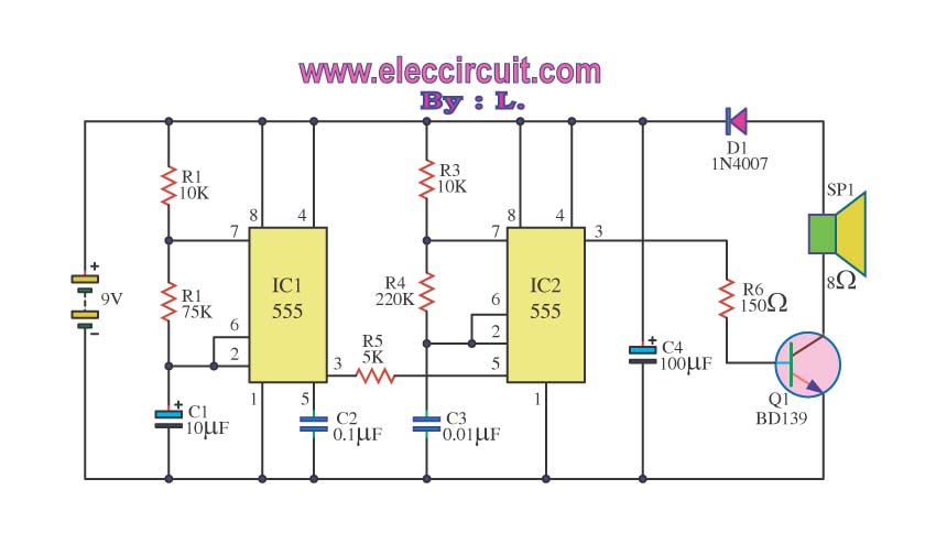
Police sirens sound with ic 555
Many people might be excited by the sound of a siren, as it is often associated with emergency events such as accidents. However, one may wonder about the underlying mechanisms that produce this alerting sound.
The siren sound commonly used in...
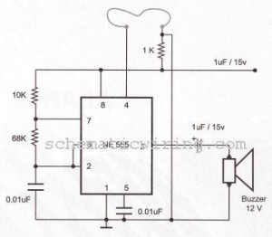
burglar alarm using ic timer 555556
The circuit of a burglar alarm utilizing IC timer 555/556 functions as a security measure to prevent unauthorized entry into a premises. The alarm generates a loud sound when a thin wire connecting resistor R1 with pin 4 of the...
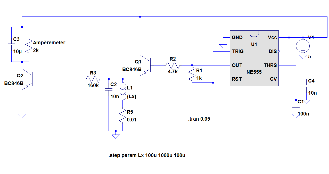
Inductivity Meter Using IC 555
The objective of the project is to construct a simple, low-cost inductance meter. The primary components of the project include an IC 555, a transistor, a resistor, and a capacitor.
The inductance meter designed in this project utilizes the IC 555...

Voltage Test Probe
Using inexpensive components, you can fit a simple probe circuit into a pencil-sized enclosure. When both LEDs are on, the probe indicates the presence of an ac voltage; either LED alone indicates the presence and polarity of a dc voltage....
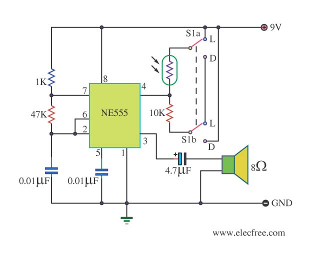
Light Dark Detector Alarm by IC 555
This circuit detects light and provides a voice warning. It responds to changes in light conditions, becoming active based on the position of switch S1.
The circuit utilizes a light-dependent resistor (LDR) to sense ambient light levels. When the light intensity...
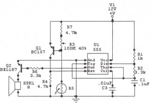
Light Alarm (Sun Up Alarm)
The IC 555 Light Alarm (Sun Up Alarm) circuit is designed to emit a loud alarm at dawn, particularly for individuals who struggle to wake up, even with a traditional alarm clock. The circuit is modifiable.
The IC 555 timer is...
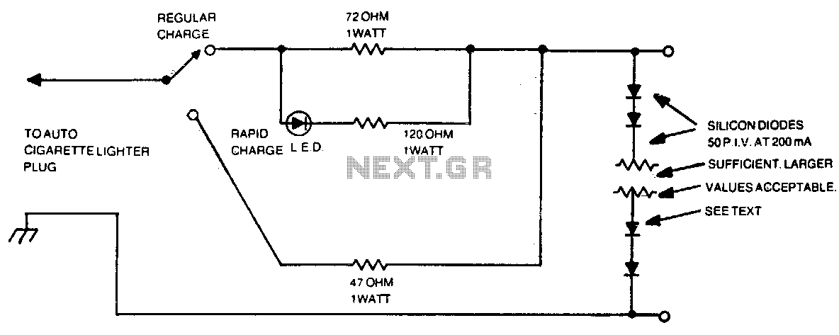
Automotive charger for ni-cad battery packs
The number of silicon diodes across the output is determined by the voltage of the battery pack. Each diode is considered at 0 volts. For example, a 10-volt pack would require 10/0 = 157, or 16 diodes.
In the context of...
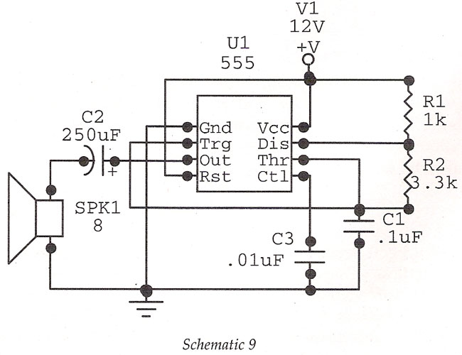
1.8 KHz IC 555Basic Oscillator
Basic Oscillator (Tone Generator) at 1.8 kHz using IC 555. This circuit features an astable oscillator configuration built around the 555 timer IC, generating an alarm tone of 1.8 kHz that directly drives a speaker. This is a fundamental alarm...
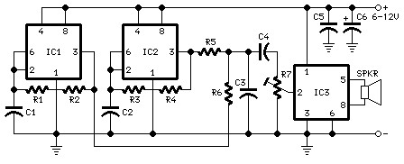
The schematic diagram fo Car Horn using IC 555
The following diagram is the schematic diagram for a car horn circuit, which can be utilized for car modifications. Components List: R1 = 68K, R2 = 2K2, R3 = 56K, R4 = 3K3, R5, R6 = 4K7, R7 = 10K...